Schwank ThermoControl Plus 2 User Manual
Page 26
- 26 -
6.6.3 Zone Configuration – Luminous (high intensity) Heaters
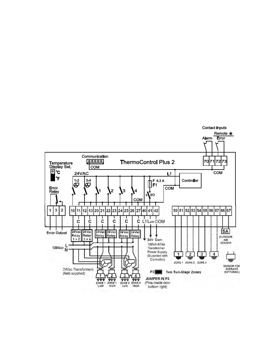
JUMPER IN POSITION 3 (P3): Two two-stage zones
The jumper pins P1 to P3 are located inside the controller cover to the right side of the battery. The
location of the jumper in P1 … P3 determines the quantity of single-stage and two-stage zones.
With the jumper in position P3, both zones are two-stage. Four relay switches are supplied with
the controller to switch line voltage to the zone transformers (field supplied).
Two additional field supplied relay switches (P/N: JS-0568-CC) are required to power the exhaust
fans for the two-stage zones. Refer to Section 6.7.
The fans for the two-stage zones are controlled by the controller fan outputs 10-11 and 12-13.
The 120V/24Vac zone transformer is ‘sized’ to provide sufficient power to all heaters in the zone:
40VA for first heater + 20 VA for each additional heater. A separate transformer is required for
each of the Low- and High-stage zones in two-stage Zones 1 and 2.
Refer to the diagram below, and the wiring diagram “Luminous Heaters – Two-Stage Zone”.
Zone exhaust fans
(field supplied)
* One additional field
supplied relay switch
(for exhaust fan) is
required for each two-
stage zone