Schwank ThermoControl Plus 2 User Manual
Page 24
- 24 -
exhaust fan and transformer in each zone. Heating zone required exhaust volume is:
USA: 4 cfm/1,000 Btuh input; Canada: 300 cfm/100,000 Btuh input. Zone transformer sizing: 40VA
first heater + 20VA each additional heater in zone.
The configuration diagrams below indicate the single- and two stage zone strategies for Jumper
positions P1 to P5. Also refer to the wiring diagram for luminous heaters in Section 8.
6.6.1 Zone Configuration – Luminous (high intensity) Heaters
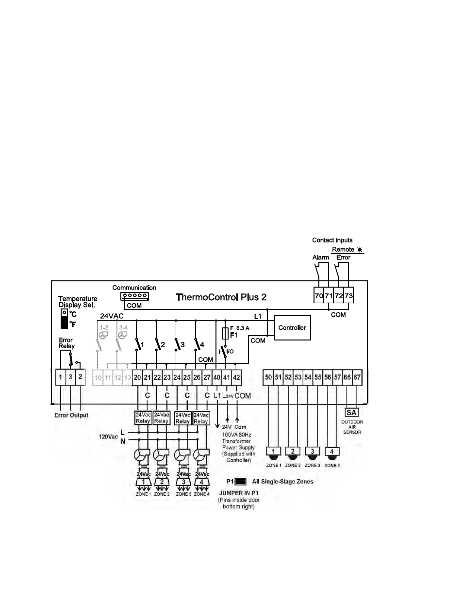
JUMPER IN POSITION 1 (P1): Up to four single stage zones (all single-stage)
The jumper pins P1 to P3 are located inside the controller cover to the right side of the battery. The
location of the jumper in P1 … P3 determines the quantity of single-stage and two-stage zones.
With the jumper in position P1, all zones are single stage. Four relay switches are supplied with the
controller to switch line voltage to the zone exhaust fans (field supplied) and to the zone
transformers (field supplied). Single-stage zones are controlled by the heater outputs 10-27.
Single-stage zone exhaust fans are wired in parallel to the heater zone transformer.
The 120V/24Vac zone transformer is ‘sized’ to provide sufficient power to all heaters in the zone:
40VA for first heater + 20 VA for each additional heater.
Refer to the diagram below, and the wiring diagram “Luminous Heaters – Single-Stage Zones”.
Zone exhaust fans
(field supplied)
DO NOT USE
FAN OUTPUTS
(SEE SECTION
5.2)
FAN OUTPUTS
FOR TWO-
STAGE
LUMINOUS
ONLY