D15 male, Signal, Navigation buttons – SATEC PM174 Quick Start User Manual
Page 6
The typical installation diagram above shows a 4-Wire Wye 2½-element connection using
2 PTs and 3 CTs. The wiring mode is 3LL3 or 3Ln3. The voltages must be balanced for
the configuration to provide accurate power measurements.
There are approximately nine different wiring configurations in the PM17X Series. Refer
to the Installation and Operational Manual for additional configurations.
For electrical installation of the display panel follow the following steps:
1. Connect the remote display using the pinout for a self-powered display or a
remote powered display. Refer to the Installation and Operation Manual for the
wiring schematic diagrams.
Pinout for a self-powered remote display
PM174
D15 Female
Pinout
Signal
Remote Display
D15 Male
Pinout
1
+12V
1
5
RS-485 + (plus)
5
7
RS-485 - (minus)
7
8
GND
8
15
Chassis
15
Pinout for a remote display powered from an external 12V DC, 350
mA power source
PM174
D15 Female
Pinout
Signal
Remote Display
D15 Male
Pinout
1
N.C.
+12V
1
5
RS-485 + (plus)
5
7
RS-485 - (minus)
7
8
N.C.
GND
8
15
Chassis
15
2. Connect the DC or AC power.
3. Connect the chassis ground.
4. Connect the required wiring configuration.
5. Connect the I/O connections as required. For I/O ratings, see the Technical
Specifications section in the Installation and Operation Manual.
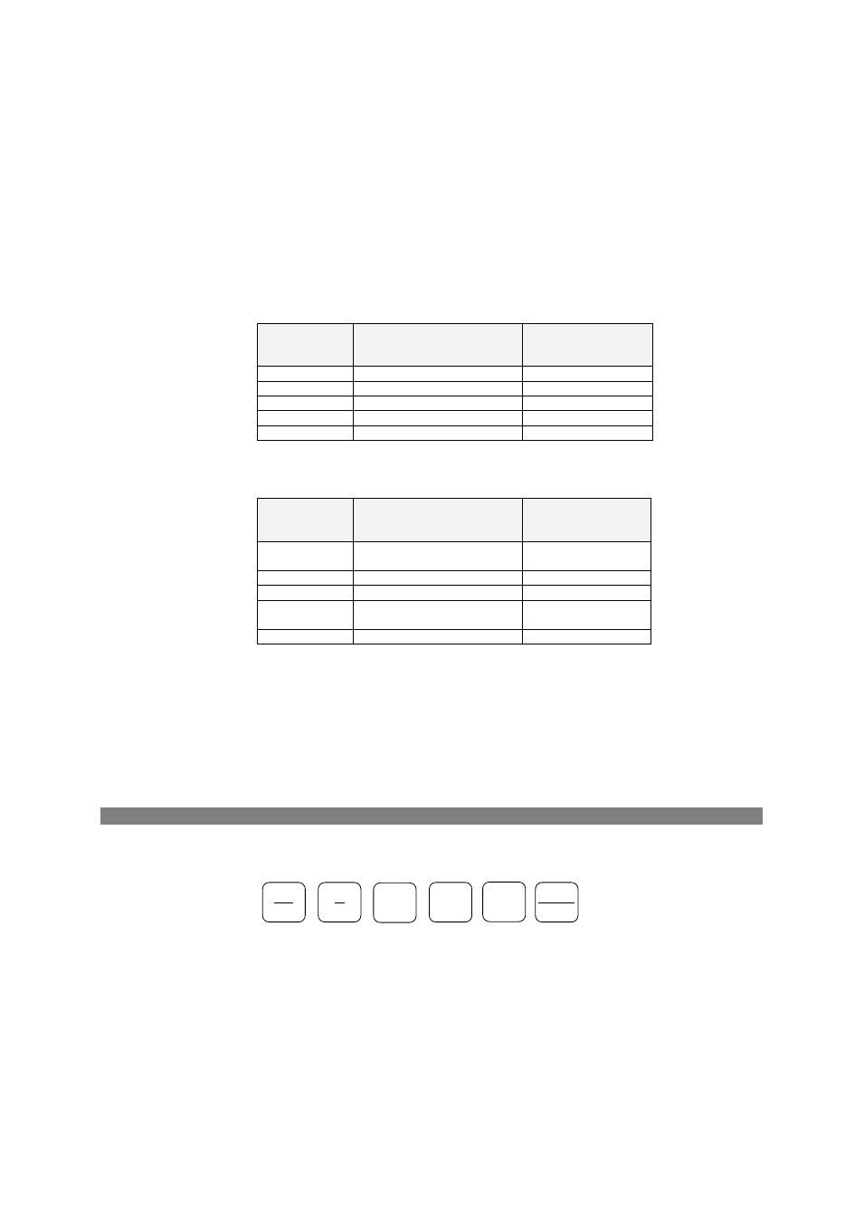
Navigation Buttons
Setup is performed directly from the display panel or via communication ports using PAS
communication software.
In Data Display mode, the navigation buttons function as follows.
The MIN/MAX button switches to the Min/Max Maximum Demands display pages. When
briefly pressed again, it switches back to the common measurements display.
The PQ button switches between different power quality/harmonic displays: Total
Harmonics, Individual Voltage and Current Harmonics, and Power Quality parameters –
short-term (Pst) and long-term (Plt) flicker, and voltage and current negative sequence
unbalance. When briefly pressed once again, it switches back to the common
measurements display.
ENERGY
ENTER
PQ
ESC
MIN
MAX
SELECT
BG0452 REV.A5
6