Modbus menu – RKI Instruments Digester Gas Monitor User Manual
Page 76
70 • Using the Digester Gas Monitor in a 4-wire Modbus System
Digester Gas Monitor Operator’s Manual
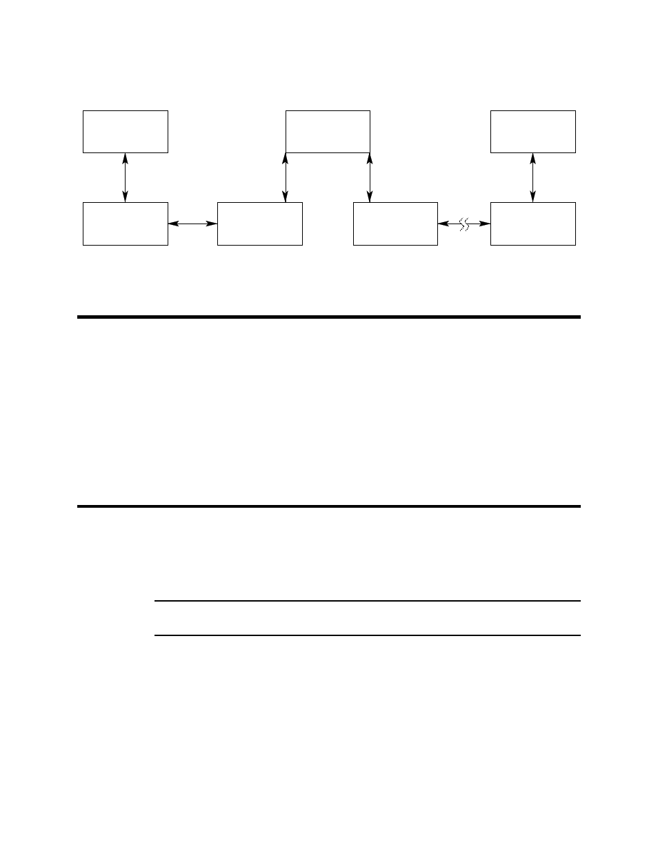
Figure 22: Multiple Digester Gas Monitors in a Two Branch Configuration
Using the Digester Gas Monitor in a
4-wire Modbus System
Although the Digester Gas Monitor is a 2-wire Modbus RTU device, it can be used with a
4-wire Modbus controller if the system wiring is modified as follows:
•
Connect the controller’s TxD0 and RxD0 wires together and use this connection as
the 2-wire Modbus D0 signal.
•
Connect the controller’s TxD1 and RxD1 wires together and use this connection as
the 2-wire Modbus D1 signal.
•
Connect these D0 and D1 signals and the common wire from the controller to the 2-
wire Modbus Network of Digester Gas Monitors.
Modbus Menu
The Modbus Menu allows you to configure various parameters relating to the Modbus
setup of the Digester Gas Monitor. The Modbus Menu includes a 5-minute timeout feature.
If you do not press a control switch for 5 minutes, the Digester Gas Monitor automatically
returns to Standby Mode.
NOTE: If the Digester Gas Monitor returns to Standby Mode because of a timeout, it
enters a warm-up period just as it does when it is first turned on.
1.
While in Standby Mode, simultaneously press and hold the ENTER and DOWN/NO
buttons for approximately 5 seconds to enter the Modbus Menu. Release the buttons
when the
You Have Entered the MODBUS Menu
message appears on the display.
Digester Gas Analyzer
Termination Jumper
Installed
ID=4
ID=31
ID=32
Digester Gas A nalyzer
Termination Jumper
Installed
RS-485
Modbus Master
Up to 32 Digester Gas A nalyzers can be connected without a repeater
ID=3
Digester Gas Analyzer
Termination Jumper
Not Installed
Digester Gas Analyzer
Termination Jumper
Not Installed
Digester Gas A nalyzer
Termination Jumper
Not Installed
Digester Gas A nalyzer
Termination Jumper
Not Installed
ID=2
ID=1
RS-485