RKI Instruments Digester Gas Monitor User Manual
Page 18
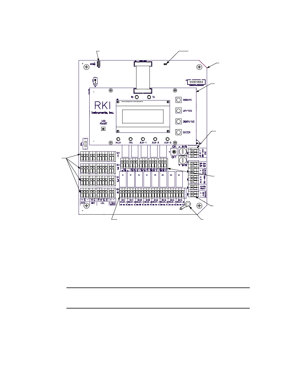
12 • Internal Description
Digester Gas Monitor Operator’s Manual
Main PCB
This section describes the components of the main PCB.
Figure 5: Main PCB Component Location
Terminal Strips
The Digester Gas Monitor includes 9 terminal strips for wiring connections. See “Wiring
the Digester Gas Monitor” on page 23 for detailed wiring procedures.
•
Strobe Terminal Strip
The strobe terminal strip is a 2-point terminal strip located in the upper left corner of
the main PCB. When the optional horn/strobe is ordered with a Digester Gas Monitor,
the strobe terminal strip is used to wire the horn/strobe.
CAUTION: The strobe terminals are intended for use with the RKI supplied optional
horn/strobe. Consult RKI Instruments, Inc. before attempting to use these
terminals for any other alarm device.
•
Detector/Transmitter Terminal Strips
Four detector/transmitter terminal strips are located along the bottom left side of the
Ground Stud
Controller
Terminal Strip
Control PCB
Main PCB
Detector/
Transmitter
Terminal
Strips
Common/
Channel A larm
Terminal Strip
Termination Jumper
AC In
Terminal Strip
Strobe Terminal Strip
Channel A larm Terminal Strip