Chapter 2: description, Overview, External description – RKI Instruments Digester Gas Monitor User Manual
Page 11
Digester Gas Monitor Operator’s Manual
Overview • 5
Chapter 2: Description
Overview
This chapter describes the Digester Gas Monitor’s external and internal components.
External Description
This section describes the housing and all external components of the Digester Gas
Monitor. For the purposes of this description, the housing door is considered the front of
the monitor.
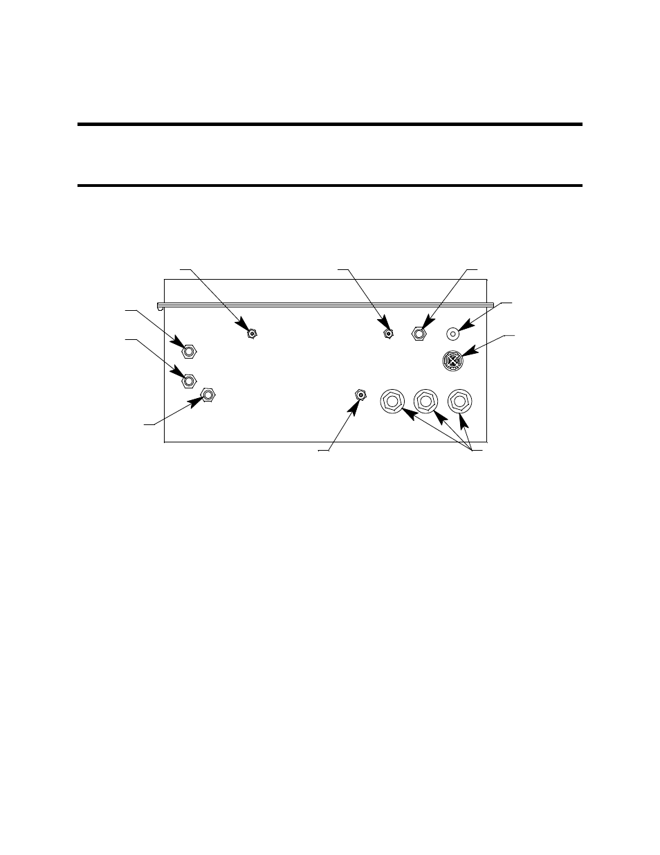
Figure 1: External Component Location
Housing
The Digester Gas Monitor’s fiberglass housing is weather- and corrosion-resistant. It is
suitable for installation where general purpose equipment is in use. The housing door is
hinged on the left side and is secured by two latches on the right side. The LCD display,
status LEDs, and flowmeters are visible through the window in the housing door. Four
mounting feet are attached to the back of the housing (one at each corner). The mounting
feet allow you to install the housing to a vertical surface. These mounting feet are not
installed as shipped from the factory (see “Mounting the Digester Gas Monitor” on page 22
for instructions to install the mounting feet). Three conduit hubs on the bottom of the
housing are for external wiring connections.
Reset Switch
The reset switch is on the bottom right of the housing in front of the buzzer. The reset
switch serves four functions:
•
Resets the alarm circuits for “latched” alarms after an alarm 1, alarm 2, or alarm 3
condition passes.
You can set each channel for latched or self-resetting alarms in the Configuration
Menu. See “Viewing and Changing Channel Parameters” on page 51 for more
information.
Buzzer
Fresh Air Inlet
Reset Switch,
Push Button
Dryer
Exhaust
Conduit Hub, 3/4"
Aspirator/Sample, Exhaust
Compressed
Air Inlet
Blow Back Exhaust
Calibration Gas Inlet
Digester
Sample