Display pcb – RKI Instruments Digester Gas Monitor User Manual
Page 16
10 • Internal Description
Digester Gas Monitor Operator’s Manual
Display PCB
The display PCB (printed circuit board) is mounted to the power supply mounting plate
which is in turn mounted to the main PCB. The power supply mounting plate and main
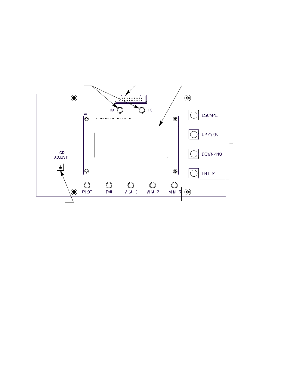
PCB are described below. The display PCB includes the LCD display, the LCD contrast
adjust pot, the status LEDs, and the control switches. It is connected to the main PCB by
the display cable which is a 20 conductor ribbon cable assembly. The display cable
connects to a rectangular connector on the top edge of the display PCB and to the same
type of connector labelled “FRONT PANEL” on the top edge of the main PCB.
Figure 4: Display PCB Component Location
LCD Display
The four line display indicates gas readings and shows messages, settings, and other
data when you are operating the various selection menus and operating modes.
LCD Contrast Adjust Pot
The LCD contrast adjust pot is located to the left of the LCD. If the LCD contrast is too
dark or too light to read easily, use a small phillips screwdriver to adjust it until you can
easily read the LCD.
Status LEDs
The Digester Gas Monitor includes seven status LEDs that indicate the current status of
the monitor: the RX & TX LEDs, the pilot LED, the fail LED, the alarm 1 LED, the alarm 2
LED, and the alarm 3 LED (see Figure 4).
•
RX & TX LEDs
These LED’s indicate data is being received (RX) and transmitted (TX) when the
Digester Gas Monitor’s Modbus output is operating.
•
Pilot LED
The PILOT LED is on when the Digester Gas Monitor is receiving incoming power,
Status LEDs
LCD Contrast
Adjust Pot
LCD Display
Display Cable
Connector
Status LEDs
Control
Switches