Recommended modbus wiring, Termination jumper, Figure 20: recommended modbus wiring – RKI Instruments Digester Gas Monitor User Manual
Page 75
Digester Gas Monitor Operator’s Manual
Wiring the Digester Gas Monitor in a Modbus System • 69
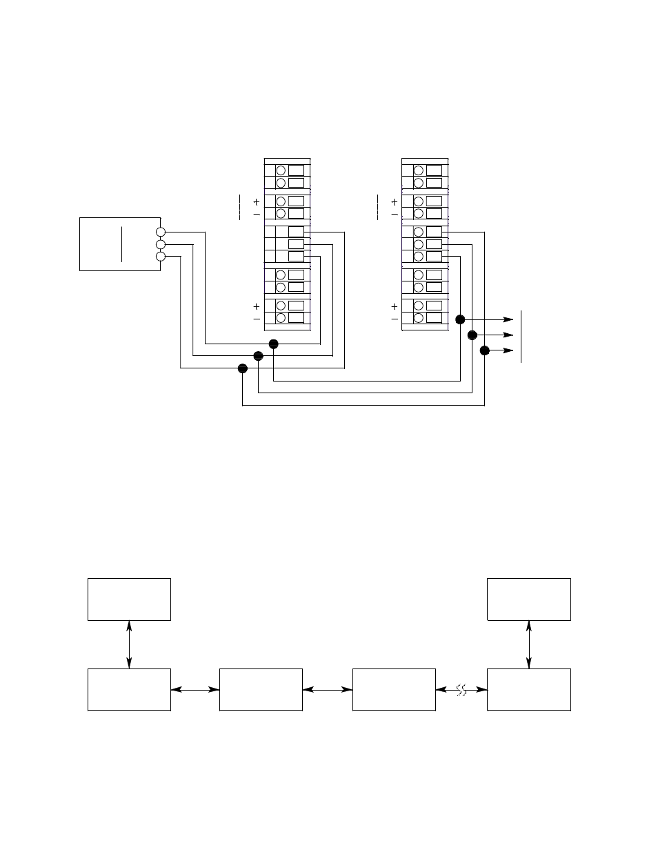
Recommended Modbus Wiring
The recommended Modbus wiring for the Digester Gas Monitor is illustrated in Figure 20
below.
Figure 20: Recommended Modbus Wiring
Termination Jumper
The Digester Gas Monitor includes a 2-pin termination header (see Figure 3) that may
need to be installed when the Digester Gas Monitor is used in a Modbus system. Every
Digester Gas Monitor is supplied with a termination jumper (a jumper block) installed onto
this header. If the Digester Gas Monitor is not used in a Modbus system, this jumper has
no function. When the Digester Gas Monitor is installed in a Modbus system, this jumper
must be installed in a Digester Gas Monitor that is at the end of a Modbus line. Any
Digester Gas Monitor in a Modbus system that is not at the end of a line must have the
termination jumper removed (see Figure 21 & Figure 22 below).
Figure 21: Multiple Digester Gas Monitors in a Daisy Chain Configuration
B
A
DP SW
DP SW
E
X
T
D
C
24
V
B
A
T
T
B
A
DP SW
DP SW
E
X
T
D
C
24
V
B
A
T
T
Digester G as A nalyzer
Controller Terminal S trip
Digester G as A nalyzer
Controller T erminal S trip
Common
D1
AL
A
R
M
BU
Z
Z
E
R
ALARM
RESET
AL
A
R
M
BU
Z
Z
E
R
ALARM
RESET
Modbus
Controller
C
RS
-4
8
5
To Additional
Digester Gas
Analyzers
Input
Terminals
D0
C
RS
-4
8
5
ID=1
ID=29
Modbus Master
RS-485
Up to 32 Digester Gas A nalyzers can be connected without a repeater
ID=30
Digester Gas A nalyzer
Termination Jumper
Not Installed
Digester Gas A nalyzer
Termination Jumper
Not Installed
Digester Gas A nalyzer
Termination Jumper
Not Installed
Digester Gas A nalyzer
Termination Jumper
Not Installed
ID=31
RS-485
ID=32
Digester Gas A nalyzer
Termination Jumper
Installed