RKI Instruments 12 VDC Beacon 200 User Manual
Page 13
12 VDC Beacon 200 Operator’s Manual • 9
•
DC In Terminal Strip. The DC in terminal strip is a 3-point terminal strip
located above the controller terminal strip (see Figure 1). It facilitates
wiring from a 12 VDC power source. Table 4 lists the function of each
terminal.
Relays
The 12 VDC Beacon 200 includes four channel relays (two per channel)
and three common relays. Both sets of relays are single-pole, double-throw
(SPDT) and are rated for 10 amps at 250 VAC (resistive).
NOTE: You can select normally energized (NE) or normally de-energized
(NDE) settings for each channel in the Channel Control and Setup
program. This section describes the default setting: normally de-
energized.
The alarm 1 and alarm 2 common relays are factory-set as NDE
and the fail common relay is factory-set as NE. The alarm 1, alarm
2, and fail common relays’ NE/NDE settings are not user-
adjustable.
•
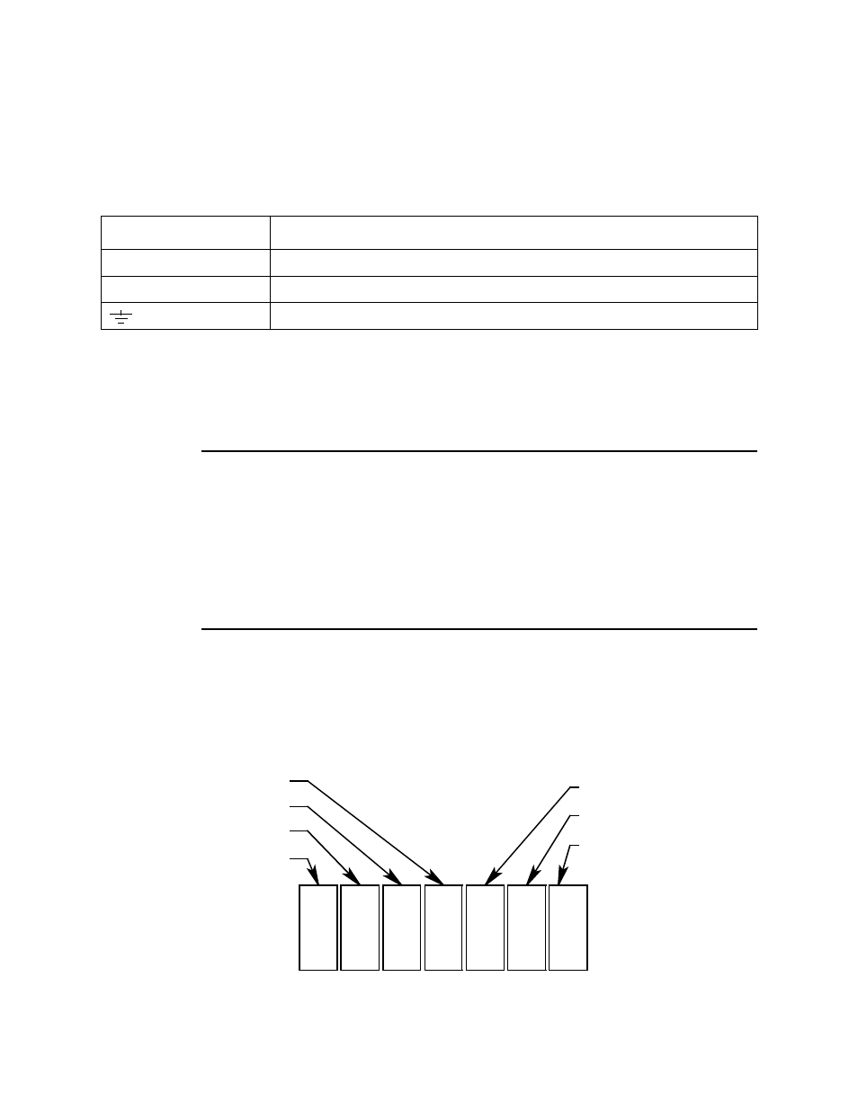
Channel relays. The four channel relays are above the alarm terminal
strip (see Figure 1). These relays are dedicated to specific channels
and alarm levels.
For example, the channel 1, alarm 1 relay energizes if channel 1
recognizes an alarm 1 condition. Figure 2 below illustrates the
allocation of the channel relays.
Table 4: Terminal Assignments for the AC In Terminal Strip
Terminal
Connects to:
12 VDC +
+ wire from 12 VDC power source
12 VDC -
- wire from 12 VDC power source
Earth ground
K5
K6
K7
Channel 2, Alarm 1
Channel 1, Alarm 2
Channel 1, Alarm 1
K1
K2
K3
Common Alarm 1
Common Alarm 2
Common Fail
K4
Channel 2, Alarm 2
Figure 3. 12 VDC Beacon 200 Channel Relay Allocation