Sdm-2012, Control panel – RKI Instruments SDM-2012 Standalone Configuration User Manual
Page 16
11 • Control Panel
Control Panel
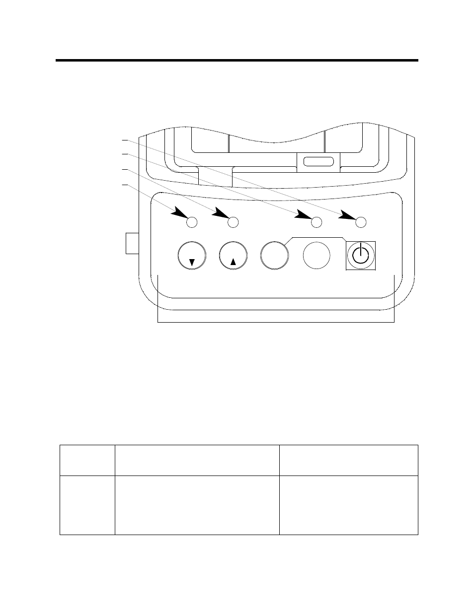
The control panel is used to setup and operate the docking station in the Standalone
configuration. It is located at the front of the docking station. It includes the control
buttons, the control button LEDs, and the CHARGE status LED.
Five control buttons are located on the control panel. From left to right they are BUMP
T
, CAL
S
, EDIT ENTER, COPY, and POWER. The BUMP
T
, CAL
S
, and COPY
control buttons each have an LED above them that indicates the status of the function
controlled by that button. The CHARGE LED is located above the POWER button
and functions as a pilot LED, a system failure LED, and a charge indication LED.
Table 2: Control Button Functions
Control
Button
Control Button Function(s)
Control Button LED
Function(s)
BUMP
T
• Initiates a bump test
• Cancels a bump test
• Moves down a list of parameters
• Decreases an adjustable
parameter
Indicates status of a bump test
in progress
COPY
1SEC ON
3SEC OFF
CHARGE
POWER
GX-2012 OFF
BUMP
SDM-2012
CAL.
Control Buttons
EDIT
ENTER
BUMP LED
CHARGE LED
COPY LED
CAL LED
Figure 11: Control Panel