Wiring and plumbing diagram, aux channel, Wastegate – Precision Turbo and Engine NLR AMS-1000 Boost Controller User Manual
Page 21
21
B A
C
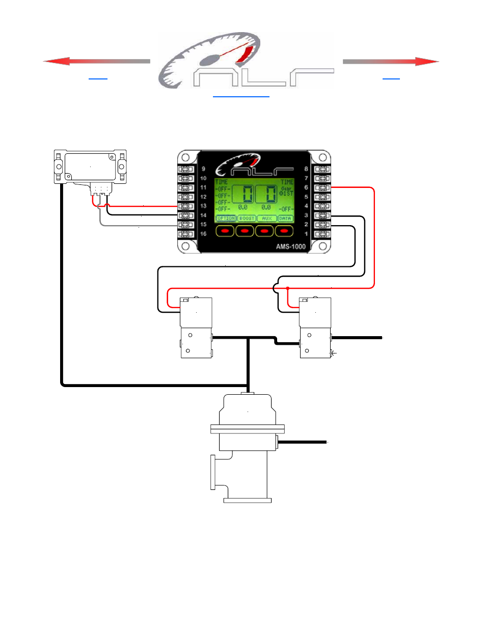
+5V
GND
OUT
12223861
MAP Sensor +5V
MAP Ground
MAP Signal, Aux Channel
OUT
EXH
IN
OUT
EXH
IN
Increase
Solenoid
Decrease
Solenoid
1/8 NPT
Plug
Air Supply or
Manifold Pressure
Solenoid +12V
Decrease Solenoid Ground
Increase Solenoid Ground
Wastegate
Manifold Pressure
Wiring and Plumbing Diagram, Aux Channel
Click for Index.
Back
Next
NOTE—Target Psi is the amount applied to the waste gate and is NOT the actual Manifold Boost Psi!