Paxton Net2 I/O board User Manual
Paxton, [email protected], Technical support
Ins-30019 Net2 I/O board
20/08/2012
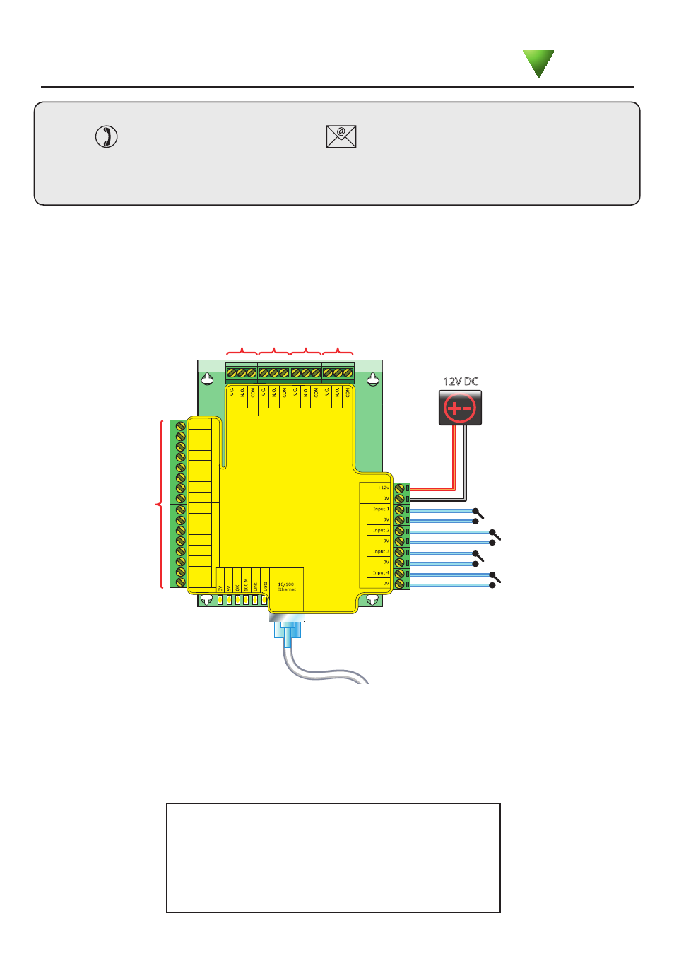
Output 1
12V DC
Power
Inputs
R
eader
2
R
eader
1
Red
Brown
Orange
Green
Yellow
Blue
Mauve
Black
Red
Brown
Orange
Green
Yellow
Blue
Mauve
Black
Relay 1
Relay 2
Relay 3
Relay 4
Input 1
Input 2
Input 3
Input 4
Output 2
Output 3
Output 4
Input terminal (FOR FUTURE USE)
Patch lead
Diagnostic LED's
Net2 I/O Boards are configured to switch their relays by setting up a 'Triggers and Actions' rules.
Four inputs are provided to allow connection to door contacts, etc, without the need of a Net2 ACU.
Four output relays are also provided to switch a variety of AC and DC output devices. The relay
contacts are rated at 13A at 240V AC, to enable mains voltages to be switched.
Technical Support
Technical help is available: Monday - Friday from 07:00 - 19:00 (GMT)
Saturday from 09:00 - 13:00 (GMT)
01273 811011
Documentation on all Paxton products can be found on our website - http://www.paxton.co.uk/
The I/O board is a Network based product and requires connection to the PC via a TCP/IP connection.
This unit requires the controlling PC to be running Net2 v4 software.
- 3V Power LED
- 5V Power LED
- OK LED - This should flash regularly
- 100 M - On = 100 Mbit/s : Off = 10 Mbit/s
- Link - The I/O board is connected to a Network port
- Data - The I/O board is receiving ethernet data
Diagnostic LED's
Paxton