Wiring, Full system reset, Wire outputs – Paxton Vandal resistant compact metal keypad User Manual
Page 2
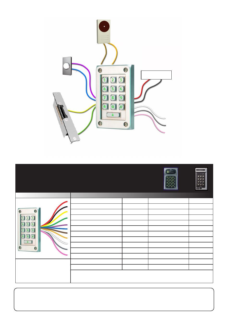
Bell
Exit
Exit button
(push to make)
Electric release
Power supply
0V
0V
0V
0V
V+
V+
V+
The combined current for all
outputs must not exceed 1A.
Wiring
Power supply
0V
Lock V+
Lock 0V
Exit input
Exit 0V
Bell V+
Bell 0V
Relay (Default - N.O.)
Relay COM
Relay (Default - N.C.)
1. Power down the system.
3. The unit will beep/flash LED's 3 times a second.
2. Power the system up whilst holding down button 3. 4. Go to - Initialising a new system.
Full System Reset
Mauve
Blue
Brown
Orange
White
Grey
Pink
Green
Yellow
Black
Red
Orange
Brown
Features not available: Tamper, Door Contact, Multiple Doors, Timers, Interlock.
Paxton
Features
ACT10
Bewator K42
Duress Alarm V+
Duress - 0V
Defining any user code as a
duress code will change the
function of the Orange and
Brown wires to a duress alarm
output and will disable the bell
button on the keypad.
Lock control is provided by both a powered
lock output and also a voltage free relay.
If the V+ lock wire (Yellow) or V+ bell wire
(Brown) are not connected they must be
terminated to avoid a short circuit.
Have you installed an ACT 10 keypad or Bewator K42?
If so, use this conversion chart to assist with the wiring change.
Wire outputs
Terminal 1
Terminal 2
Terminal 3
Terminal 4
Terminal 5
Terminal 6
Terminal 9
N/A
J4-1 +12V/24V
J4-2 -12V/24V
J2-3
Push button
J2-1
Inputs 0V
J3-2 Buzzer
J3-1
Outputs 0V
J4-3 N/C
J4-4 COM
J4-5 N/O
J3-3
OP3 Duress
J3-1
Outputs 0V
N/A
N/A
N/A
N/A
N/A
N/A
N/A
N.C.
COM
N.O.
When using the relay output, it is not recommended to
use the 'Lock wire setting' in the 'fail open' mode.