D-sub, High density connectors technical characteristics – Northern Connectors Harting D-sub Connectors, Housings & Accessories User Manual
Page 37
05
36
D-Sub
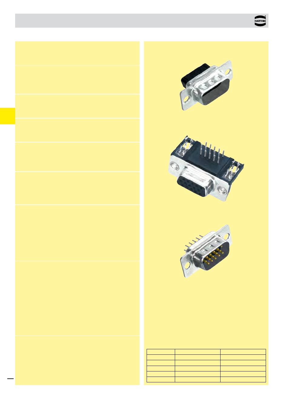
D-Sub
high density connectors
Technical characteristics
1)
Performance level 3, 50 mating cycles, no gas test
S4, plating = 0.76 µm (30 µinch) Au or PdNi equivalent
Shell size
D-Sub standard
D-Sub high density
1
9
15
2
15
26
3
25
44
4
37
62
5
50
78
Number of contacts in the D-Sub standard/D-Sub high density
range related to the shell size.
Number of contacts
15, 26, 44, 62, 78
Working current
Stamped contacts
2 A max.
Test voltage U
r.m.s.
1 kV
Clearance and creepage
≥ 1.0 mm
Contact resistance
< 20 mΩ
< 25 mΩ (for right angled versions)
Insulation resistance
≥ 5 x 10
9
Ω
Temperature range
-40
O
C … + 85
O
C
The higher temperature limit includes the local ambient and
heating effect of the contacts under load
Terminations
a) Solder pins Ø 0.65 mm for
P.C.B. holes Ø 1.0 mm
b) Crimp contacts
AWG 26 - 24
0.14 - 0.22 mm²
max. insulation Ø 1.38 mm
c) Solder cups
AWG 24
Materials
Mouldings and hoods
Thermoplastic resin, glass-
fibre filled (PBTP),
UL 94-V0
Contacts
Copper alloy
Contact surface
Contact zone
selectively plated according
to performance level
1)
Metal shell
Plated steel
Mating force
15 way ≤ 46 N
26 way ≤ 77 N
44 way ≤ 127 N
62 way ≤ 177 N
78 way ≤ 222 N