Vr-36ha — service information – Multiquip VR36HA User Manual
Page 61
VR-36HA • VIBRATORY ROLLER — PARTS & OPERATION MANUAL — REV. 6 (06/13/06) — PAGE 61
VR-36HA — SERVICE INFORMATION
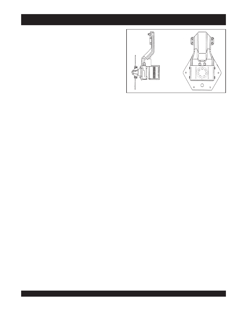
3.10 Drive Motor Installation
1.
Install the drive motor to the drum support using
Locktite
271
on all bolts.
2.
Install the key and install the drive hub. Using
Locktite 271
secure the retaining nut to 300 - 400 ft. lbs. of torque (a
proper retaining device is necessary to hold the hub).
3.
Install the drive plate using
Locktite 271
on all bolts.
4.
Install the hydraulic lines (do not tighten).
5.
Install the drive / support assembly to the drum using
Locktite 271
on all bolts and nuts.
6.
Install the drum support to frame bolts using
Locktite 271.
7.
Remove the caps and connect the hydraulic lines to the
bulk head fittings. Tighten all lines (upper and lower).
8.
Test operate and check for hydraulic leaks.
3.11 Rear Drum Removal
1.
Park the roller on a hard flat surface, connect the center
joint locking arm, and chock the front drum.
2.
Remove the drain / fill plug and drain any ballast in the
drum.
3.
Using a proper lifting device, lift the rear of the roller using
the provided lifting eyes.
4.
Remove the retaining bolts from the right side drum bearing
block.
5.
Disconnect and cap the hydraulic lines of the left side.
6.
Remove the retaining bolts on the left drum support bracket.
7.
Lubricate the O-ring and install it inside of the hub.
8.
Install the hub in its bore making sure that it seats properly
(a proper pressing device may be required).
9.
Install the oil seal inside of the bearing carrier with the seal
lip facing the vibrator housing.
10. Install the bearing cage into the carrier and install the snap
ring.
11. Place the vibrator shaft assembly into the housing.
12. Coat the top of the vibrator housing with
Locktite 515
.
13. Using guide bolts install the vibrator housing.
14. Install the retaining bolts using
Locktite 271.
15. Pour 16 ounces of SAE 30W engine motor oil into the
housing through the drain / fill hole. Replace the plug.
16. Refer to previous sections to reinstall vibrator assembly.
3.8 Installing Front Drum
1.
Using caution, roll the front drum under the machine using
care to position in the proper location.
2.
Using caution, lower the front frame to the proper height.
3.
Rotate the drum supports and install the Allen head cap
screws using
Locktite 271
and torque to 95 Ft. Lbs.
4.
Connect all hoses and lines.
5.
Test operate and inspect for any leaks at the hydraulic
fittings.
3.9 Drive Motor Removal
1.
Using a proper lifting device, elevate the left side of the
machine and secure with jack stands.
2.
Disconnect the hydraulic lines from the top fittings and install
caps.
3.
Remove the retaining bolts from the drive plate to drum.
4.
Remove the left side drum support retaining bolts and
remove the complete drive / support assembly.
5.
Remove the hydraulic pipe guard and remove the hydraulic
pipes.
6.
Remove the retaining bolts from the drive motor drive hub
and remove the drive plate.
7.
Remove the large nut from the drive end of the drive motor.
8.
Using a proper pressing device, press off the drive hub.
9.
Remove the retaining bolts and remove the drive motor
from the drum support.