Vr-36ha — service information – Multiquip VR36HA User Manual
Page 53
VR-36HA • VIBRATORY ROLLER — PARTS & OPERATION MANUAL — REV. 6 (06/13/06) — PAGE 53
VR-36HA — SERVICE INFORMATION
1.5. Hydraulic System
A good quality hydraulic oil should be used.
DO NOT USE MULTI-VISCOSITY OIL. Cleanliness is a very
important part of proper hydraulic system operation. Hydraulic
oil is not only used to transfer power; it also lubricates and cools
the system components. Keeping the hydraulic system clean
can help reduce costly repairs.
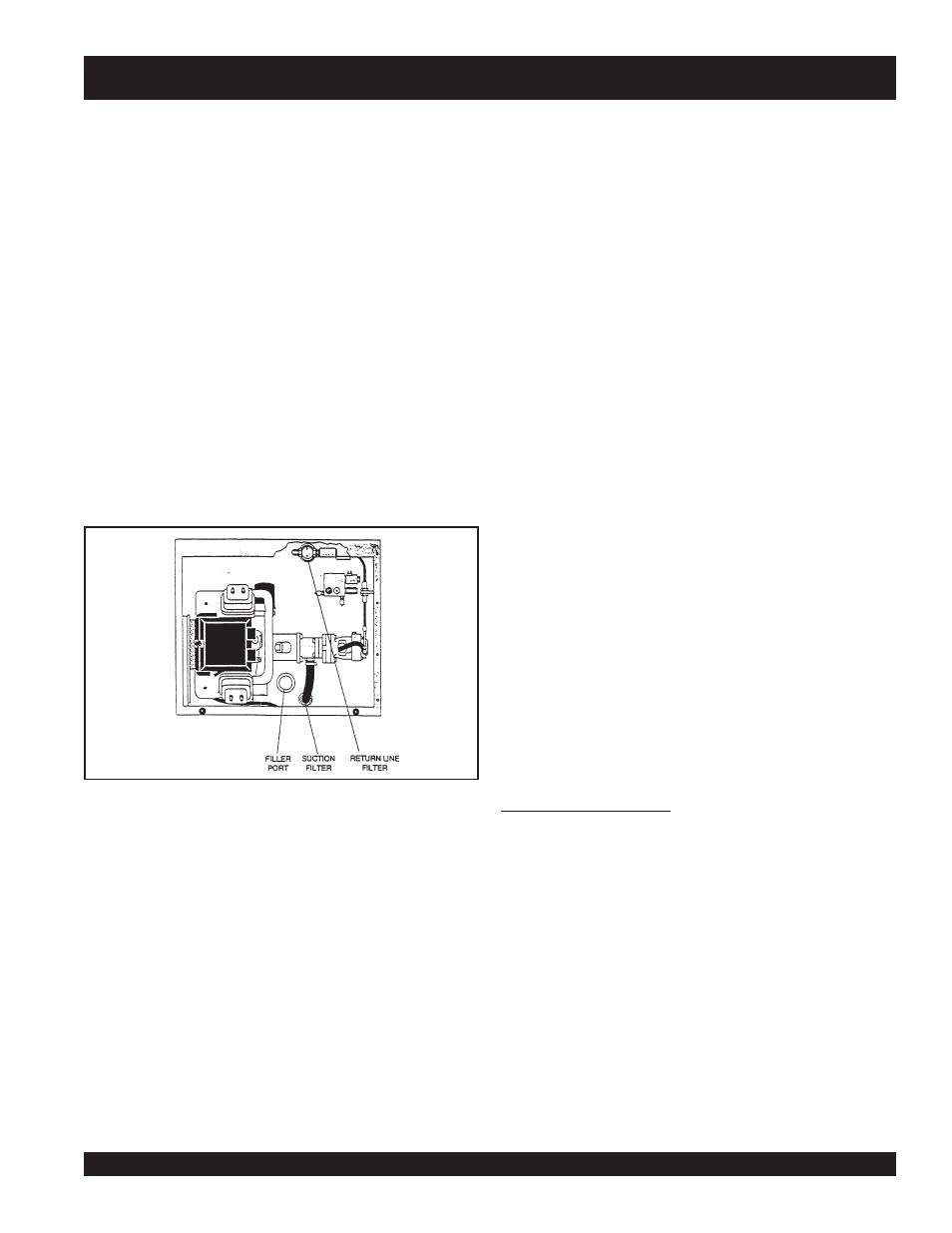
The hydraulic oil level sight glass is located on the right rear of
the front drum, below the engine compartment. This level should
be checked daily. Oil must be below the top and above the bottom
of the sight glass. DO NOT OVERFILL! Care should be taken to
clean the filler cap before adding oil to the system. If hydraulic oil
has to be added, the machine should be inspected for leaks.
The suction filter is located in the hydraulic tank. This filter is
attached to the fitting connected to the hydraulic pump suction
hose.
The return filter is located at the front of the engine compartment.
Replace both filters according to the service chart.
1.6. Changing Hydraulic Oil And Filters
1.
Park the machine on a clean flat work area and set the
parking brake.
2.
Remove the drain plug and drain the hydraulic oil. Dispose
of the used oil in an environmentally friendly manner.
Replace the drain plug and tighten.
3.
Remove the return filter and install a new
filter. Dispose of the used filter in an environmentally friendly
manner.
4.
Disconnect the suction hose and remove the fitting from
the tank. Replace the suction filter. Dispose of the used
filter in an environmentally friendly manner. Replace the
fitting and reconnect the suction hose.
5.
Fill the hydraulic tank with the proper quantity and quality
required. See service chart for specifications.
6.
Place the forward / reverse control lever in the neutral
position. Start and run the engine at idle for approximately
3 to 5 minutes.
7.
Recheck the oil level and fill as required.
1.7. Scraper Bars And Cocoa Mats
The scraper bars are located on the rear of the front drum and
the front of the rear drum. Adjust the scrapers, using the slotted
holes provided. as close as possible to the drums.
The cocoa mats are located at the front of the front drum and the
rear of the rear drum. Cocoa mats should be replaced when
badly worn. Always pre-wet the cocoa mats before use.
1.8. Towing Valve
The hydraulic system has a towing valve allowing hydraulic oil
to by-pass. This lets the unit freewheel for emergency towing.
The towing valve should only be used in emergencies when the
machine cannot be driven due to engine or hydraulic system
problems.
When towing is complete, this valve
must
be closed completely
and the lock nut set. Failure to close this valve completely will
result in low power, improper speed, and excessive hydraulic oil
temperature.
WARNING: The towing valve is only for emergency use.
DO
NOT
tow unit over 2 MPH or long distance as hydraulic system
component failure could result.
2.0 HYDRAULIC SYSTEM
2.1 General
The hydraulic system consists of a two pump stack directly
coupled to the engine. A hydraulic valve block is provided for
quick and easy testing and troubleshooting.
Hydraulic oil is filtered by a screen filter located in the tank filler
neck, a 40 micron suction filter located in the tank, and a 10
micron return filter, with cold oil bypass valve located in the return
circuit.