Vr-36ha — service information – Multiquip VR36HA User Manual
Page 59
VR-36HA • VIBRATORY ROLLER — PARTS & OPERATION MANUAL — REV. 6 (06/13/06) — PAGE 59
VR-36HA — SERVICE INFORMATION
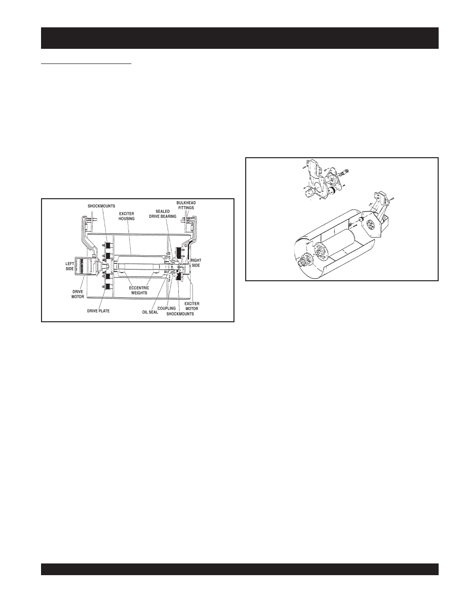
3.0 Drums and Main Frame
The front drum is designed to apply vibration and compaction
force to the operating surface for compaction. This vibration and
compaction force is produced when the vibrator shaft is rotated.
Maximum efficiency is achieved only when the engine is operated
at full throttle.
A single drive motor is mounted on the left side of the drum and
is shockmounted. This type of drive motor is designed for
maximum torque and power.
The vibrator is driven by a gear motor coupled to the vibrator
shaft. The vibrator assembly rotates inside of a sealed housing
containing oil to lubricate the bearings. This side of the drum is
also shockmounted.
3.1 Removing Front Drum
The drum assembly and all attaching hardware should be
cleaned before any work is performed.
1.
Park the roller on a clean, flat, hard surface. Set the parking
brake and chock the rear drum.
2.
Set the center joint locking arm.
4.
Disconnect all hydraulic hoses and lines.
5.
Using a proper lifting device, slightly lift the front frame
using the lifting eyes provided on the front of the frame.
6.
Remove the Allen head cap screws retaining the drum
support plates.
7.
Using caution, lift the front frame until the front drum can be
rolled out from under machine.
3.2 Front Drum Disassembly
1.
Remove the front drum as per section 3.1.
2.
Remove the drive motor assembly complete with the drum
support plate and drive plate.
3.
Remove the vibrator drive motor and the drum support plate.
4.
Stand the drum on end with the vibrator drive facing up.
5.
Remove the vibrator motor mount plate.
6.
Remove the snap ring which retains the vibrator bearing
housing.
7.
Remove the vibrator cover.
8.
Remove the vibrator shaft using care not to damage the
bearings.
9.
Inspect, repair or replace parts as required.
3.3 Front Drum Assembly
1.
Cover the inside of the bearing housing with a light coat of
oil. Install the drive bearing.
2.
Install the bearing housing on the hub of the vibrator
assembly, and press down until the bearing seats against
the hub shoulder.
3.
Install the snap ring.
4.
Install the vibrator motor assembly onto the motor mount
using
Locktite 271
and tighten all bolts.
5.
Install the motor mount assembly to the bearing housing
using
Locktite 271
and tighten all bolts.