Vr-36ha — service information – Multiquip VR36HA User Manual
Page 57
VR-36HA • VIBRATORY ROLLER — PARTS & OPERATION MANUAL — REV. 6 (06/13/06) — PAGE 57
VR-36HA — SERVICE INFORMATION
B. Adjusting Drive Relief Valves
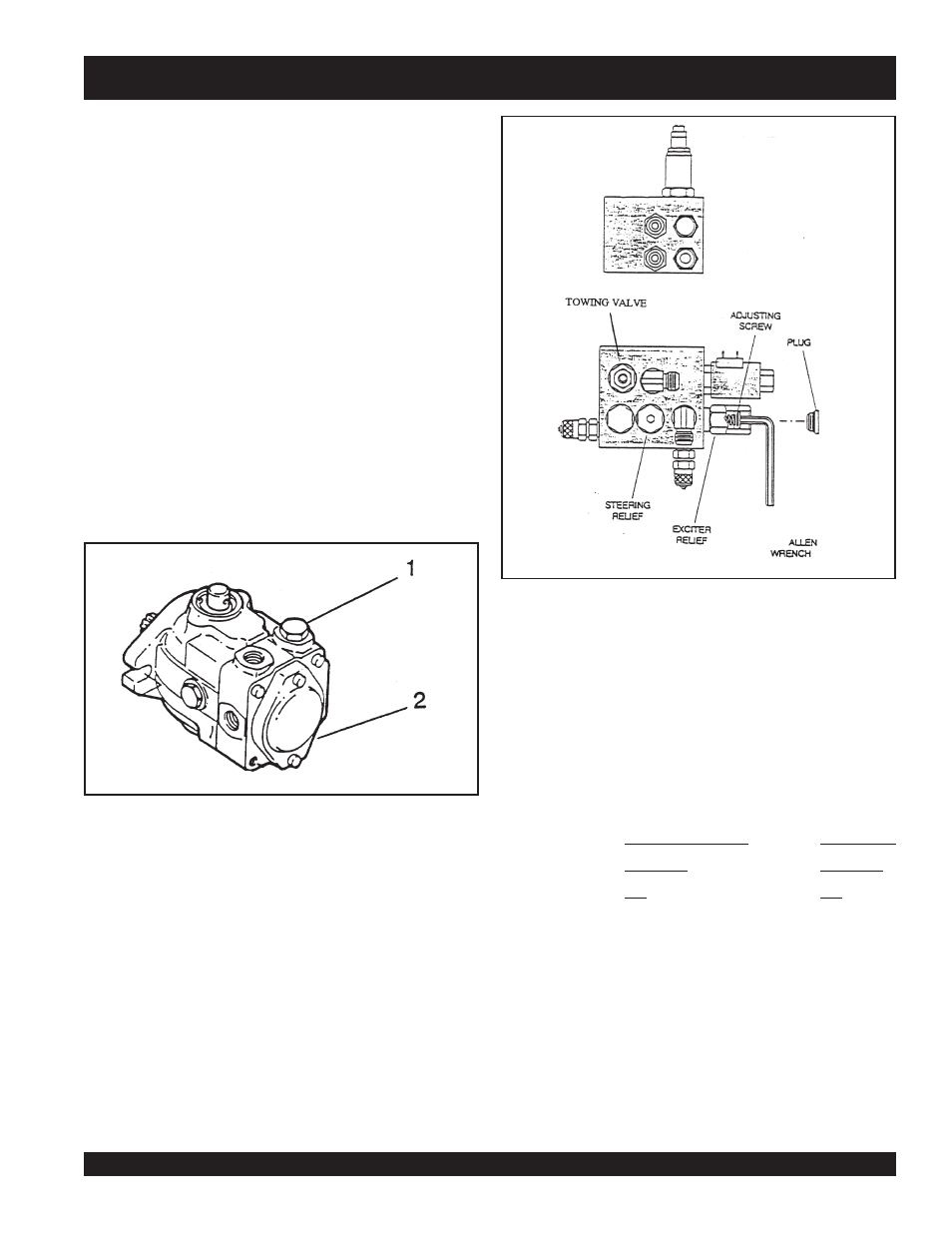
The forward and reverse relief valves are shim type cartridge
type and are located in the hydrostatic pump under caps #1 and
#2 (cap #2 is located in the same location as #1, except it is on
the bottom of pump). Relief valve #1 is Reverse; #2 is Forward.
1.
Clean the area around the cap.
2.
Remove the cap.
3.
Carefully remove the valve cartridge.
4.
Using an Allen wrench, remove the top nut (extreme care
must be taken not to loosen existing shims, spring, or valve)
Add or subtract shims as required (adding shims increases
pressure; subtracting shims lowers pressure. One shim is
equal to approximately 50 PSI).
5.
Install the top nut and install valve in the pump cavity using
extreme care not to bind.
6.
Install the valve cap.
7.
Re-test pressure, further adjustment may be needed if
pressure is not correct.
C. Vibration Circuit Pressure
Place the front drum on soil, gravel, or a heavy rubber mat.
DO NOT RUN VIBRATION ON CONCRETE OR HARD
SURFACE!
1.
Install a 5000 PSI gauge to the quick connect.
2.
Start the engine and run at full throttle.
3.
Turn ON the vibration. Pressure will read “relief pressure”
on initial vibration start up and then “return to normal
operating pressure”.
Vibration relief pressure is hard to read accurately using this
test. It may be necessary to disconnect the pressure line to the
vibration drive motor. Plug this line and re-test, pressure will be
exact relief pressure. DO NOT PERFORM THIS TEST FOR A
LONG PERIOD OF TIME - DAMAGE COULD OCCUR.
D. Steering Circuit Pressure
1.
Install a 1000 PSI gauge to the quick connection.
2.
Start the engine and run at full throttle.
3.
Turn the steering wheel to maximum and hold. Read the
steering relief pressure.
If maximum pressure cannot be reached, plug the steering
cylinder pressure hoses and re-test. If pressure is correct the
steering cylinder is leaking. DO NOT OPERATE THE
VIBRATION WHILE PERFORMING THIS TEST !
Normal Operating
Relief Valve
Pressure
Pressure
PSI
PSI
Forward .............. 400 - 600 ................................ 2900
Reverse ............... 400 - 600 ................................ 2900
Vibration .............. 800 - 1000 .............................. 2000
Steering ............... 200 - 500 ................................ 500
2.7 Removing & Replacing Hydrostatic Pump Assembly
1.
Set the parking brake.
2.
Disconnect the battery.
3.
Clean the pump and all connections.