MTS Series 256 Servovalve User Manual
Page 25
Series 256 Servovalve Product Information
Installation
25
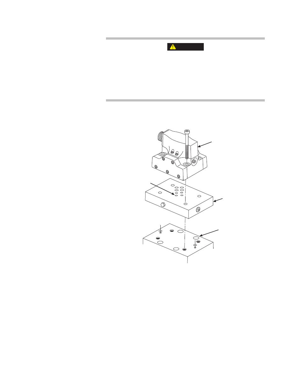
The alignment pin ensures that the servovalve assembly is properly
positioned over the hydraulic ports.
Failure to correctly align the locating pin and locating hole can result in
injury to personnel, or damage to equipment.
Ensure that the locating pin on the bottom of the servovalve is correctly positioned
within the locating hole of the actuator, manifold, or secondary servovalve.
4. Install the pilot stage onto the manifold, aligning the locating pin (as shown
in the following figure).
5. Lubricate the mounting screws with a light film of hydraulic fluid. Tighten
the mounting screws to 24.40 N·m (18 lbf·ft). As you tighten the screws,
those previously tightened will lose clamping force. Continue tightening
until all screws are at the specified torque.
6. Connect all hydraulic supply and return lines.
7. Connect control cables between the servovalve and the system controller,
including a valve drive cable to the pilot stage and a inner loop feedback
cable to the LVDT in the third stage.
8. Turn on system electrical power and hydraulic power.
9. Apply low hydraulic pressure to the servovalve so that the hydraulic fluid
will fill the filter cavities gradually.
WARNING
Pilot Stage
Manifold
Main Stage
Hole for
Pilot Stage
Locating Pin