Servovalve at rest – MTS Series 256 Servovalve User Manual
Page 15
Series 256 Servovalve Product Information
Introduction
15
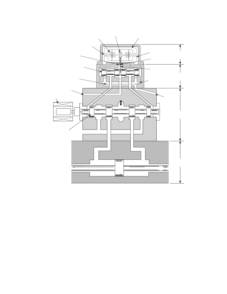
Functional Diagram
Servovalve at rest
The servovalve’s controlling element is the torque motor, which receives an
electrical input from the controller. A flapper is attached to the armature of the
torque motor. The flapper moves from side to side as the armature moves in
response to control signals from the controller. The flapper assembly is
mechanically attached to the armature. There are two nozzles, one on each side of
the flapper.
Because the nozzle-flapper valve is the first control point of hydraulic fluid, it is
called the first stage. As long as there is no command for actuator motion, the
flapper is centered between the two nozzles.
At the same time, pressurized hydraulic fluid entering the valve is applied
equally to both sides of the spool, which does not move. This is the second stage.
MP-G046H-2
Return
Pressure
Pilot
Pressure
Third
Stage
Second
Stage
First
Stage
Fixed Orifice
Feedback
Spring
Lower
Polepiece
Flapper
Core
Third (Main)
Stage Spool
LVDT
Transformer
Pilot
Return
Filter
Second (Pilot)
Stage Spool
Nozzle
Armature
Coil
Magnet
Upper Polepiece
Hydraulic
Actuator