Related products, About the servovalve, Servovalve functional – MTS Series 256 Servovalve User Manual
Page 14: Control signal, About the servovalve 14 servovalve functional 14
Series 256 Servovalve Product Information
14
Introduction
Related products
The Series 256 Servovalves includes a Series 252 Servovalve. See the Series 252
Servovalve Product Information manual (part number 011-182-906) for product-
specific information and maintenance procedures for the Series 252 Servovalve.
About the Servovalve
The heart of a servohydraulic system is the servovalve. It is the final control
element in most MTS closed-loop systems. The servovalve responds to
command signals generated by the software and processed by the controller and
output through the valve driver module. The servovalve regulates the direction
and flow of the hydraulic fluid entering the actuator from the hydraulic pressure
ports. The direction that the spools move determines the direction of fluid flow to
the actuator. A pressure difference is what causes the fluid to move.
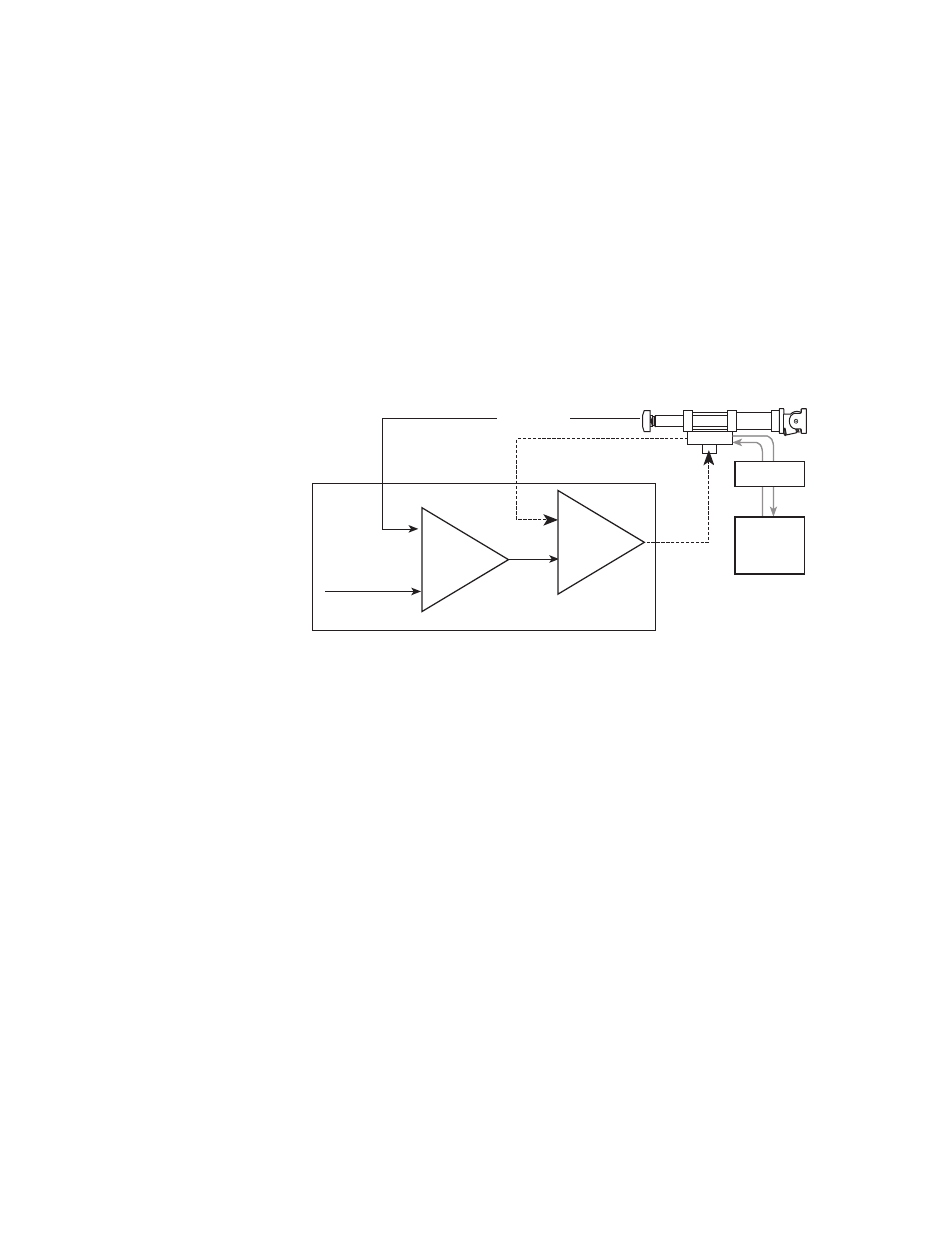
Typical Closed-Loop System
Servovalve Functional
Control signal
In a closed-loop hydraulic system, the Product Name uses the control signal from
an electronic control device (controller) to operate a valve that regulates the
movement of a hydraulic actuator.
The control signal is created by comparing the program command signal (the
desired actuator position) and the feedback signal from a transducer (the actual
actuator position). Any difference between the two is called DC error, which is
the command to the servovalve to supply hydraulic fluid to the actuator until the
desired actuator position is achieved.
Test
Command
Control
Signal
Inner
Loop
Outer
Loop
Manifold
Hydraulic
Power
Unit
Valve Driver
Feedback
Controller
Control
Mode