Component identification, Component identification 14 – MTS Isolation Service Manifold Controller User Manual
Page 14
Isolation Service Manifold Controller
14
Component Identification
Hardware Overview
Component Identification
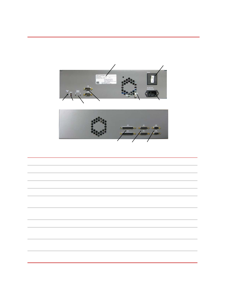
Refer to the following table for information on the components shown below.
Number
Component
Description
1
Power switch
Switch - Turns electrical power on (I) and off (O)
2
Main power in
Jack (2) and strain relief (2A) - 100-240 VAC, 50/60 Hz, 4-2 Amps
3
ID plate
Label - Identification label provides component specific information.
4
J1A/B
Connector, 9-pin D, male - refer to
5
Fault Reset A/B
Mini switch - Used to reset a fault (providing the fault has been
corrected).
6
Fault A/B
Indicators - Indicate various fault conditions depending on flashing
sequence.
7
Power OK
Indicator - Indicates the unit is on and power is satisfactory.
8
J3A/B
J3A=Channel A; J3B = Channel B. Connector 25-pin D, female - refer to
9
J2A/B
J2A=Channel A; J2B = Channel B. Connector 15-pin D, female - refer
to
10
J28A/B
J28A=Channel A; J28B = Channel B. Connector 9-pin D, female - refer
to
10
9
8
7
6
5
4
3
2A
2
1