Series 642 bend fixture component identification – MTS Series 642 Bend Fixtures User Manual
Page 14
Series 642 Bend Fixtures Product Information
14
Introduction
The 642.01, 642.10, and 642.25 can be configured for three-point or four-point
loading. Four-point loading uses two roller block assemblies in the upper
bedplate and two in the lower bedplate. Three-point loading uses two roller block
assemblies in the lower bedplate and a three-point option kit attached to the load
cell.
Different diameter rollers can be used with the same roller block assemblies.
Standard roller diameters are 0.125, 0.250, 0.375, 0.500, 0.750, 1.0, 1.25, 1.5,
1.75, and 2.0 inch, as well as 5, 8, 10, 12, 20, 30, 40, and 50 millimeter (see the
tables on pages 14–18 for individual model standard diameters). MTS can also
build rollers with custom sizes. See your sales representative if you require
rollers of non-standard size.
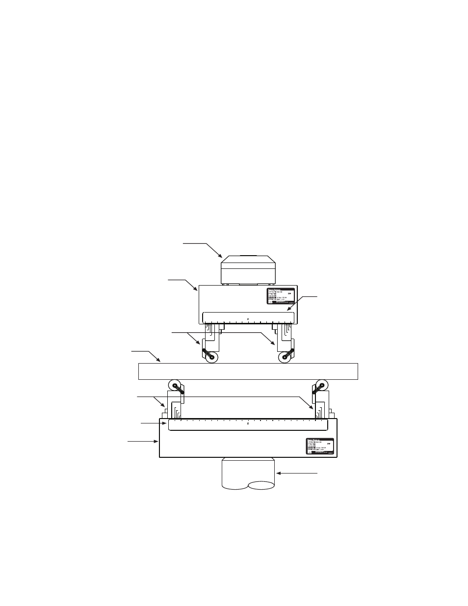
Series 642 Bend Fixture Component Identification
The following illustrations identify the Model 642 Bend Fixture’s major
components in various models and configurations.
Series 642 Bend Fixture Major Components—Four-Point Loading Configuration
Force Transducer
Upper Bedplate
Adjustable Roller Blocks
Upper Scale
Actuator
Lower
Bedplate
Lower Scale
Adjustable Roller
Blocks
Specimen