Where – MTS Series 609 Alignment Fixture User Manual
Page 35
Calculating Bending Strain—Round Thin Diameter
Series 609 Alignment Fixture Product Information
Specimen Preparation
35
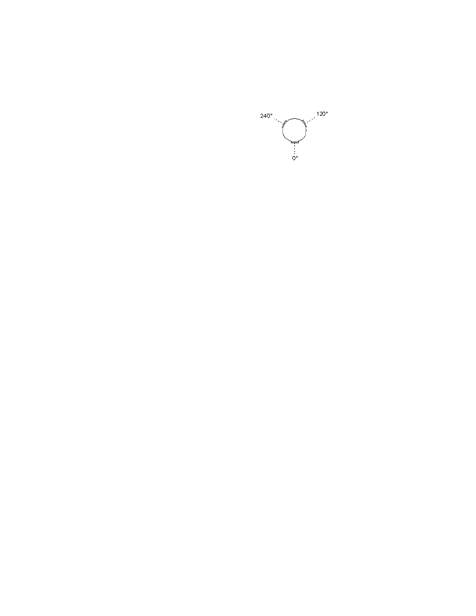
Calculating Bending Strain—Round Thin Diameter Specimens
This section shows how to calculate the bending strain for round specimens with
three gages at each level.
Gage Placement
1. Calculate the average axial strain for each level.
Use this formula to find the average axial strain (A):
Where:
ε
1
through
ε
9
are the strain readings from gages 1 through 9
Au is the average strain of the upper gages
Am is the average strain of the middle gages
Al is the average strain of the lower gages
2. Calculate the bending strain for each axis and each level.
Use these formulas to determine the bending strain (B):
Where:
ε
1
through
ε
9
are the strain readings from gages 1 through 9
bu is the bending strain of the upper gages
bm is the bending strain of the middle gages
bl is the bending strain of the lower gages
subscript
0
is the bending strain of the 0° axis
subscript
120
is the bending strain of the 120° axis
subscript
240
is the bending strain of the 240° axis
3. Determine the tensile direction for each level.
Determine the two most positive (tensile) results for each level from Step 2.
•
Call the largest b
1
.
•
Call the second largest b
2
.
Au
ε
1
ε
2
ε
3
+
+
3
----------------------------
=
Am
ε
4
ε
5
ε
6
+
+
3
----------------------------
=
Al
ε
7
ε
8
ε
9
+
+
3
----------------------------
=
Upper Gages
Middle Gages
Lower Gages
bu
0
°
ε
1
A
–
=
bu
120
°
ε
2
A
–
=
bu
240
°
ε
3
A
–
=
bm
0
°
ε
4
A
–
=
bm
120
°
ε
5
A
–
=
bm
240
°
ε
6
A
–
=
bl
0
°
ε
7
A
–
=
bl
120
°
ε
8
A
–
=
bl
240
°
ε
9
A
–
=
Upper Gages
Middle Gages
Lower Gages