Adjust concentric alignment, Adjust concentric alignment 16 – MTS Series 609 Alignment Fixture User Manual
Page 16
Series 609 Alignment Fixture Product Information
16
Adjust Concentric Alignment
Introduction
gage section. These higher strains are on opposite sides. It also has lower than
average bending strains at the top and bottom of its gage section, opposite the
higher strains.
Actual strain readings vary with the amount of tensile load applied to the
specimen. With zero or low tensile force applied to the specimen, tensile strain
readings can be opposite compressive strain readings. Under higher tensile force,
high tensile readings can be opposite lower tensile readings.
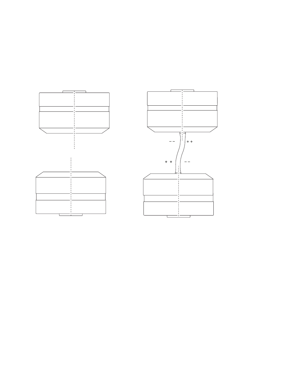
Concentric Misalignment Produces an “S” Bend
Adjust Concentric Alignment
Turning the four lower adjustment screws moves the concentricity collar. Moving
the collar laterally shifts the upper grip’s position. This aligns the grips’
centerlines, improving their concentric alignment.
The effect of improved concentricity on a specimen is to reduce its “S” bend and
the strains that go with this bend.
As “S” bend strains fade into the background, “C” bend strains come to the
foreground. (Remember that concentric and angular misalignment can occur
together, putting “S” and “C” bends into the same specimen.)
For many test procedures, removing the “S” bend alone may be enough to get
your bending strains within specifications.
Higher Than Average Strain
Lower Than Average Strain