Where – MTS Series 609 Alignment Fixture User Manual
Page 32
Series 609 Alignment Fixture Product Information
32
Calculating Bending Strain—Round Thick Diameter
Specimen Preparation
Calculating Bending Strain—Round Thick Diameter Specimens
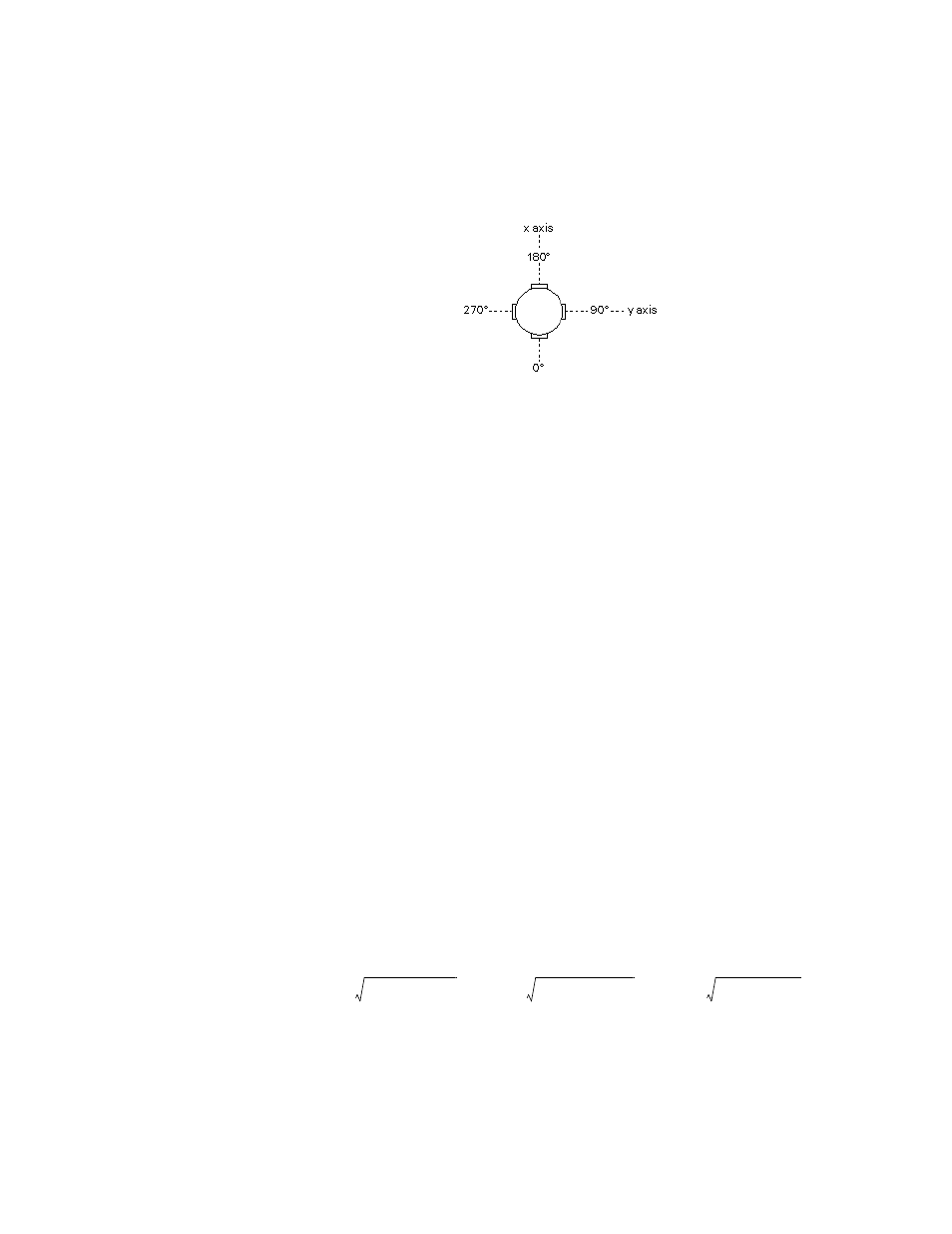
This section shows how to calculate the bending strain for round specimens with
four gages at each level.
Gage Placement
1. Calculate the bending strains for each level.
Use these formulas to find the x axis (B
x
) and y axis (B
y
) bending strains of
each level:
Where:
ε
1
through
ε
12
are the strain readings from gages 1 through 12
Bu
x
is the bending strain of the x axis of the upper gages
Bm
x
is the bending strain of the x axis of the middle gages
Bl
x
is the bending strain of the x axis of the lower gages
Bu
y
is the bending strain of the y axis of the upper gages
Bm
y
is the bending strain of the y axis of the middle gages
Bl
y
is the bending strain of the y axis of the lower gages
Do not overlook the sign of negative numbers.
2. Calculate the maximum bending strain for each level.
Use this formula to find the maximum bending strain (B):
Where:
Bu is the bending strain of the upper gages
Bm is the bending strain of the middle gages
Bl is the bending strain of the lower gages
3. Calculate the average axial strain for each level.
Bu
x
ε
1
ε
3
–
2
----------------
=
Bu
y
ε
2
ε
4
–
2
----------------
=
Bm
x
ε
5
ε
7
–
2
----------------
=
Bm
y
ε
6
ε
8
–
2
----------------
=
Bl
x
ε
9
ε
11
–
2
------------------
=
Bl
y
ε
10
ε
12
–
2
---------------------
=
Middle Gages
Lower Gages
Bu
Bu
x
(
)
2
Bu
y
(
)
2
+
=
Bm
Bm
x
(
)
2
Bm
y
(
)
2
+
=
Bl
Bl
x
(
)
2
Bl
y
(
)
2
+
=
Upper Gages
Middle Gages
Lower Gages