Protocol implementation, 5modbus implementation, 1 supported function codes – Lenze E94P PositionServo Modbus User Manual
Page 24
24
P94MOD01C
Protocol Implementation
5
Modbus Implementation
5.1 Supported Function Codes
The Modbus function codes supported by the PositionServo drive are:
03 – Read Holding Register
16 – Preset (write) Multiple Registers
5.2 Data Format, Size and Memory Area
Modbus registers are limited by protocol definition to a length of 16-bits per register. The user must use two
consecutive 16-bit registers to read/write one 32-bit register.
All PositionServo drive parameters are 32-bit in size but can be accessed in 3 different formats:
• IEEE Floating Point (FLOAT or REAL)
• 32-bit integer (DWORD or DINT)
• 16-bit integer (WORD or INT) where by the true 32-bit value consumes two consecutive 16-bit registers
Furthermore, PositionServo parameters exist in each of the 3 formats in both RAM (volatile) and EPM (non-
volatile) areas. Therefore the memory addresses are divided into six ranges according to their format and
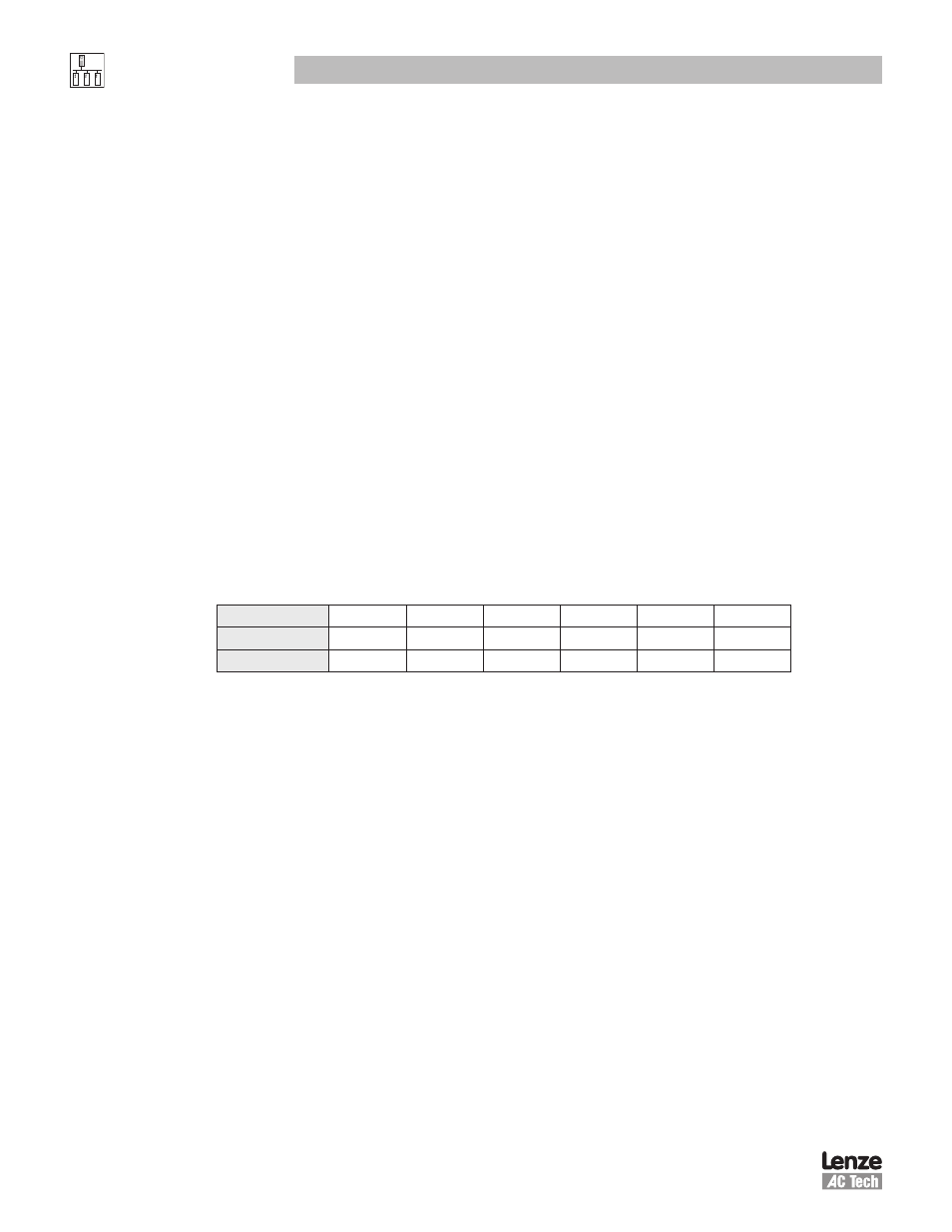
memory type as shown in Table 8.
Table 8: Memory Address Ranges
Memory Area Offset 0
512
1024
1556
2068
2304
Type
RAM
RAM
EPM
EPM
RAM
EPM
Format
32-bit INT
Float
32-bit INT
Float
16-bit INT
16-bit INT
The Modbus register address of a drive parameter can be calculated as follows:
Modbus
Register
= (2 x PID
Number
) + Memory
Offset
+ Modbus
Offset
Where:
PIDNumber =
PositionServo
Parameter Index Number. Refer to section xxxx for a full list.
MemoryOffset = Memory offset as per table 4 above
ModbusOffset = 0 for zero based addressing
1 for traditional Modbus addressing
NOTE: All values in decimal notation
To access the
(maximum address allowed is 511):
(maximum address allowed is 1023):
(maximum address allowed is 1535):