3 set node address, Set node address, Device description – Lenze ETCxxxxx User Manual
Page 18
Device description
System overview
Set node address
3.1
3.1.3
l
18
EDSTCXX EN 2.0
3.1.3
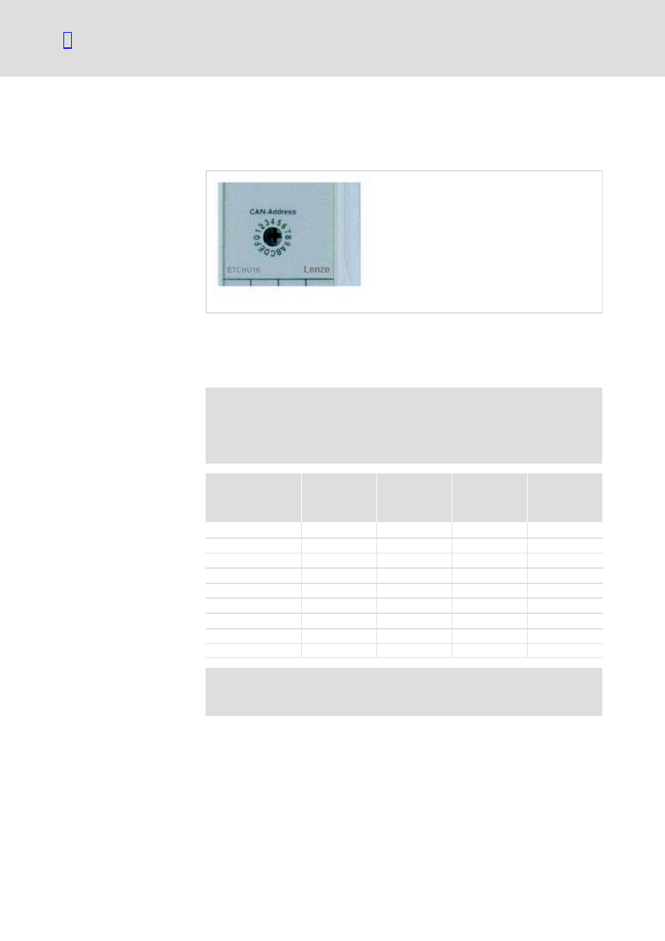
Set node address
Every ETCHx I/O module in a line represents a separate node at CAN1 bus and
must be set up with a unique node address.
ETC025
The node address is set via a front Hex switch (4 low value address bits) and
via permanently wirded bridges within the housing (3 high value address
bits). This means that a maximum of 16 modules are possible within a
module type.
)
Note!
Some modules have internal codings switches instead of the
permanently wired bridges for the optional modification of the
high value address bits.
Module type
High value
address bits
permanently
wired
Low value
address bits
adjustable at
the front
Adjustable
node address
(hex)
Adjustable
node address
(decimal)
CAN Bus Master
−−
−−
00
0
−−
−−
−−
01 H
…
0 FH
1 ... 15
ETCHU
10 H
0
…
FH
10 H
…
1 FH
16 ... 31
20 H
0
…
FH
20 H
…
2 FH
32 ... 47
ETCHA
30 H
0
…
FH
30 H
…
3 FH
48 ... 63
40 H
0
…
FH
40 H...4 FH
64 ... 79
ETCHI
50 H
0
…
FH
50 H
…
5 FH
80 ... 95
60 H
0
…
FH
60 H ... 6 FH
96 ... 111
70 H
0
…
FH
70 H ... 7 FH
112 ... 127
)
Note!
All modules at the CAN bus must have a different node address.