3 device description, 1 system overview, 1 examples for an automation system – Lenze ETCxxxxx User Manual
Page 14: Device description, System overview, Examples for an automation system, 3device description
Device description
System overview
Examples for an automation system
3
3.1
3.1.1
l
14
EDSTCXX EN 2.0
3
Device description
3.1
System overview
3.1.1
Examples for an automation system
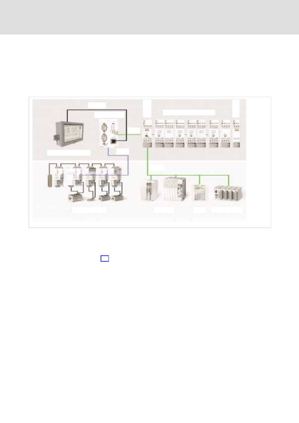
Ethernet
CAN2
CAN1
CAN-I/O
ETCHx
ETC-System Components
ETCHN003
ETCHT000
IPC with ETCPx
ECS/MCS-System
Drives
HMI
I/O-System IP20
ETCM001
The core of the automation system is the ETC control in the top hat rail design
(ETCHx) or as PCI insert card (ETCPx).
The top hat rail design ETCHx is normally used in a so−called ETC island
(
¶ 16); it communicates via Ethernet with the applications on the IPC (or
standard PC).
The ETCPC is inserted into the IPC (or standard PC) and communicates with
the applications via the PCI bus.
Both designs have two separate CAN busses:
ƒ At CAN1 bus (or also ME bus) the I/O modules and any operating
components are connected. Third party devices must comply with teh
DS401 profile of the CANopen specification.
ƒ The drives (e.g. the ECS compact servo) are connected to the connection
for the Motion CAN bus (CAN2) at the front plate. External drives must
comply with the profile DS402 of the CANopen specification and in
particular support the "Interpolated Position Mode".
ETCHx / ETCPx