6 limits, 7 compensation, 2 analog i/o – Lenze IM94MV01C User Manual
Page 19: 1 velocity limits, 2 position limits
IM94MV01C
17
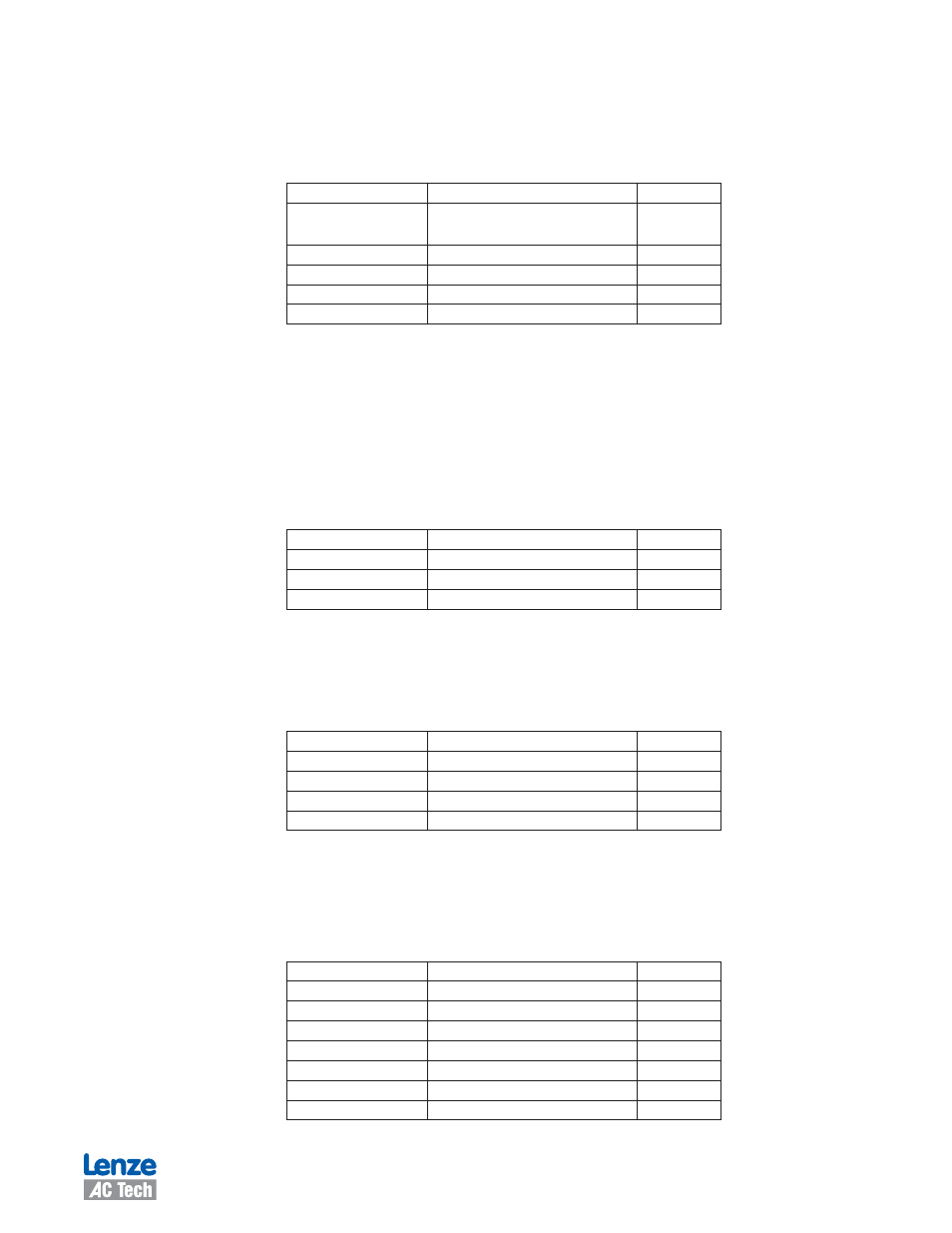
2.5.2 Analog I/O
The [Analog I/O] folder contains the parameters of one output and one input plus an action button [Adjust analog input zero
offset] that permits the user to change the analog zero offset.
Table 7: Analog Input/Output Parameters
Parameter
Range
Default Value
Analog output
Not assigned, Phase current RMS, Phase current Peak,
Motor velocity, Phase R current, Phase S current, Phase
T current, Iq current, Id current
Not assigned
Analog output current scale
0.1000 - 10.000 Volt/Amp
1.0000
Analog output velocity scale
0.1000 - 5.0000 mV/RPM
1.0000
Analog input dead band
0 - 50 mV
10
Analog input offset
-1000 - 1000 mV
0
Note: Phases R, S and T are equivalent to phases U, V and W respectively.
2.6 Limits
There are sub-folders under the [Limits] folder in the MotionView Node Tree for setting the velocity and position limits.
2.6.1 Velocity Limits
To set the velocity limits of the PositionServo drive in MotionView, double click on the [Limits] folder to expand it then click on the
[Velocity limits] folder to open this function. Table 8 lists the range and default value of each of the Velocity limits parameters.
Table 8 Velocity Limits Parameters
Parameter
Range
Default Value
Zero speed
0 - 100 RPM
10
Speed window
10 - 10000 RPM
100
At speed
-10000 - 10000 RPM
10000
2.6.2 Position Limits
To set the position limits of the PositionServo drive in MotionView, double click on the [Limits] folder to expand it then click on the
[Position limits] folder to open this function. Table 9 lists the range and default value of each of the Position limits parameters.
Table 9: Position Limits Parameters
Parameter
Range
Default Value
Position error
1 - 3767 counts
500
Max Error Time
0.500 - 8000.0000 ms
500.0000
Second encoder Position error
1 - 3767 counts
500
Second encoder Max Error Time
0.500 - 8000.0000 ms
500.0000
2.7 Compensation
To set the Compensation parameters, click the [Compensation] folder to open its contents in the List View window. To change
a compensation parameter, click the Parameter name. Table 10 lists the range and default value of each compensation pa-
rameter.
Table 10: Compensation Parameters
Parameter
Range
Default Value
Velocity P-gain
0.0000 - 3767.0000
600.0000
Velocity I-gain
0.0000 - 16383.0000
0.0000
Position P-gain
0.0000 - 3767.0000
600.0000
Position I-gain
0.0000 - 16383.0000
0.0000
Position D-gain
0.0000 - 3767.0000
0.0000
Position I-limit
0.0000 - 0000.0000 RPM
00.0000
Gain scaling
-16 - 4
-4