Function block library lenze9300servo.lib – Lenze DDS Function library 9300 Servo User Manual
Page 22
Function block library Lenze9300Servo.lib
Special functions
2.1.2
Supply−failure control (L_MFAIL)
2−12
L
Lenze9300Servo.lib EN 1.1
Commissioning of the supply−failure control
The commissioning should be carried out with motors without any load.
1. Start the drive with a FALSE−TRUE trasnsition at X5/E5 (when DIGIN_bIn5_b is connected to
bReset_b ).
2. Setting the acceleration time nTi :
– Set speed setpoint to 100%, operate controller with maximum speed.
– Inhibit controller via terminal X5/28 (you can also use any other source for the controller
inhibit, CINH) and measure the deceleration time to standstill.
– Set approx. 1/10 of the deceleration time in nTi .
3. Setting the retrigger time
– For supply−failure detection by detecting the DC−bus voltage level:
In wRetriggerTime set the run−down/deceleration time measured under point 2. .
– For supply−failure detection via an external system (e.g. supply module 934X):
In wRetriggerTime set the time for which the drive continues to be braked in a controlled
way in the event of short−term supply recovery.
4. Switch off the supply voltage (supply or DC−bus).
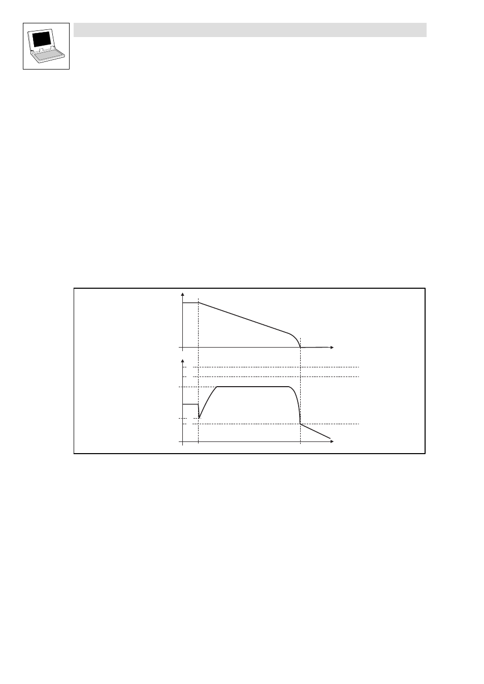
The oscilloscope should display the following sequence
U G
t 1
t 2
t
n
0
0
L _ C M P _ b O u t _ b
n D c S e t _ a
t
Q
T
S
R
Abb. 2−11
Schematic representation with activated supply−failure control (ideal characteristic)
Switch−off threshold OU
Switch−on threshold for brake unit
Threshold
Threshold LU
n
Speed of the drive
t1 Supply−failure
t2 Zero speed reached