2 connection plan, 3 connection data, Connection plan – Lenze E82ZN User Manual
Page 37: Connection data, Electrical installation
Electrical installation
Connection plan
l
37
EDK82ZN903 DE/EN/FR 5.1
6.2
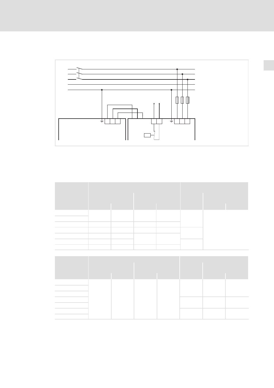
Connection plan
L1
L1
L2
L2
T1
Load
Line
E82ZZ...
E82ZN...
8200 vector
9300 vector
9300 servo
L3
L3
T2
PE
PE
L3
N
PE
L1
L2
F1...F3
K1
4
J >
8200vec107
4 Integrate the thermal contact into the monitoring system so that the mains supply is switched off when the filter is
overheated.
6.3
Connection data
Type
"Line"
(Terminals L1/L2/L3)
"Load"
(Lines with ring cable lug)
Max. conductor
cross−section
Tightening torque
Æ
Tightening torque
[mm
2
]
[AWG]
[Nm]
[lb−in]
[Nm]
[lb−in]
E82ZZ15334B230
16
6
2 ... 4
17.7 ... 35.4
M6
See documentation on
basic device
E82ZN22334B230
E82ZN30334B230
35
2
2 ... 5
17.7 ... 44.3
E82ZN45334B230
50
1/0
2 ... 6
17.7 ... 53.1
M8
E82ZN55334B230
95
4/0
6 ... 12
53.1 ... 106.2
E82ZN75334B230
95
4/0
M10
E82ZN90334B230
120
250
10 ... 20
88.5 ... 177
Type
Thermostat (terminals T1/T2)
PE (stud bolt)
Max. conductor
cross−section
Tightening torque
Æ
Tightening torque
[mm
2
]
[AWG]
[Nm]
[lb−in]
[Nm]
[lb−in]
E82ZZ15334B230
4
28 ... 10
0.6 ... 0.8
5.3 ... 7.1
M6
5
44.3
E82ZN22334B230
E82ZN30334B230
E82ZN45334B230
M8
12
106.2
E82ZN55334B230
E82ZN75334B230
M10
23
203.6
E82ZN90334B230