Mechanical installation – Lenze g500 User Manual
Page 18
Mechanical installation
Mounting
Attachment of gearboxes with hollow shafts and keyway
EN
18
Lenze ¯ MA 12.0014 ¯ 1.0
Auxiliary tool (recommended dimensions)
Æ
d
H7
d
2
c
7
18
20
M6
4
25
30
M10
5
6
35
M12
7
40
45
M16
8
9
50
55
M16
M20
10
11
60
70
M20
13
14
80
M20
16
100
M24
24
Tab. 3
Dimensions in [mm]
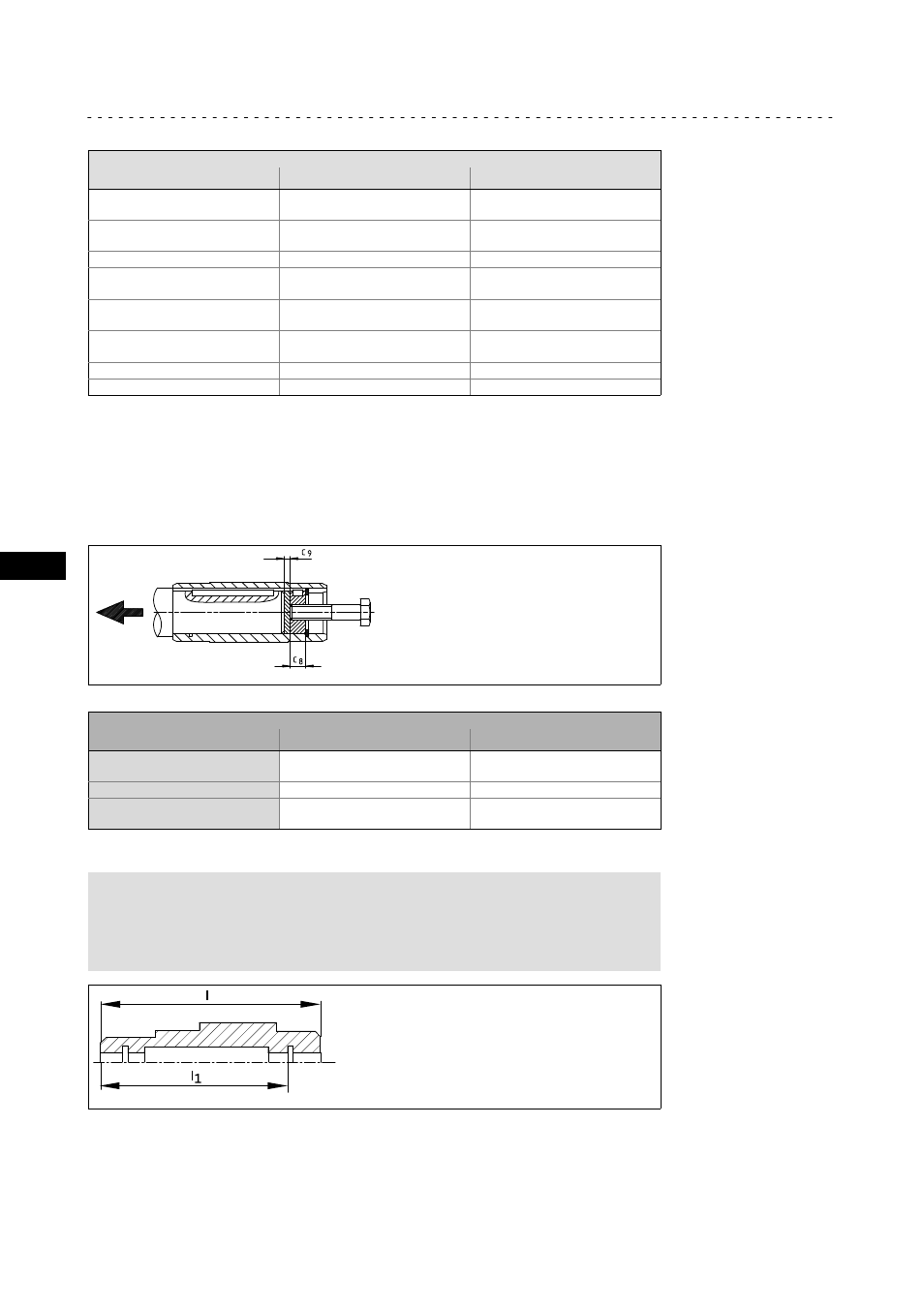
Dismounting
1. Undo axial gearbox locking in the hollow shaft.
2. Remove/extract the gearbox from the motor shaft using an appropriate auxiliary
tool (Fig. 5).
K12.0611
Fig. 5
Disassembly of gearboxes with hollow shaft, with auxiliary tool
Auxiliary tool (recommended dimensions)
Æ
d
H7
c
8
c
9
25
30
10
3
35
12
3
40
45
16
4
Tab. 4
Dimensions in [mm]
)
Note!
With the bevel gearbox, the hollow shafts are turned free in the middle
of the hollow shaft, i.e. the bore diameter is 0.1 mm higher here! A
sufficient length of the machine shaft must be observed.
- ESMD smd tmd remote keypad (4 pages)
- EPM Programmer EEPM1RA (114 pages)
- ESMDC (36 pages)
- SMD Frequency Inverter 0.37kW-22kW (116 pages)
- SMD Frequency Inverter: Basic I/O with CANopen 0.25kW-4.0kW (36 pages)
- SMD 0-25kW-4-0kW (112 pages)
- smd Series Drives (32 pages)
- ESV SMV remote keypad H0 (2 pages)
- ESV SMV remote keypad H1 (2 pages)
- SV SMV additional I-O module (14 pages)
- EEPM1RA EPM (26 pages)
- SMVector RS-485 LECOM (29 pages)
- E84AYM10S (4 pages)
- E84AYCET EtherCAT MCI module (109 pages)
- EZAMBKBM (6 pages)
- E84AYCEC (89 pages)
- ERBPxxxRxxxx Brake resistor 200W-300W (134 pages)
- E84AYCPM (115 pages)
- E84AYCEO (165 pages)
- E84AYCER (94 pages)
- E84AVSCx 8400 StateLine C (76 pages)
- EZVxxxx-000 Power supply unit AC 230V 5A-20A (62 pages)
- E84AYCIB (75 pages)
- E82ZWBRB (48 pages)
- EZVxx00−001 Power supply unit AC 400V 5A-20A (64 pages)
- E82ZWBRE (64 pages)
- EZAEBK1001 (94 pages)
- E94AYAE SM301 (134 pages)
- E94AYAE SM301 (74 pages)
- E94AYAE SM301 (140 pages)
- E94AZPS (114 pages)
- E94AYCIB (124 pages)
- E94AYCIB (78 pages)
- E94AZEX100 (84 pages)
- EZS3-xxxA200 Sinusoidal filter 115-150A (44 pages)
- E94AZHA0051 (104 pages)
- E94AZCDM030 (72 pages)
- EZS3-xxxA200 Sinusoidal filter 180-480A (74 pages)
- E94AYCCA (188 pages)
- E94AYCCA (114 pages)
- E94AZHB0101 (104 pages)
- E94AYCPM (125 pages)
- E94AYCPM (114 pages)
- E94AYCET (103 pages)
- E94AYCET (140 pages)