3 coupling hubs, Coupling hubs, Mechanical installation – Lenze g500 User Manual
Page 15: Mounting coupling hubs, En 15, 3 coupling hubs general
Mechanical installation
Mounting
Coupling hubs
EN
15
Lenze ¯ MA 12.0014 ¯ 1.0
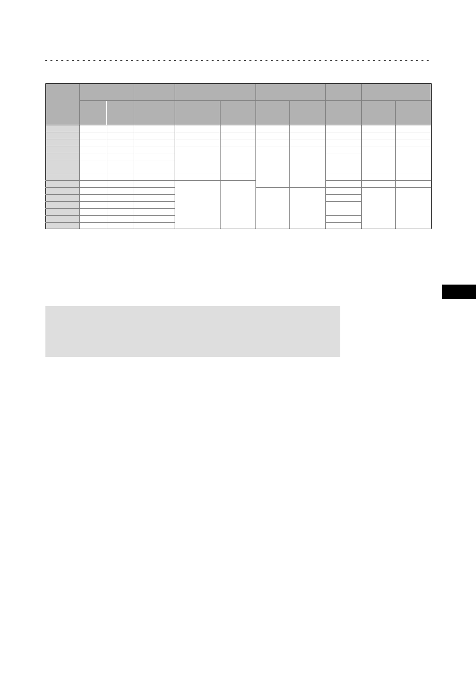
Drive size
Motor shaft
Assembly
dimension
Standard hub
Locking screw
Clamping hub
Key
1)
Clamping ring hub
D
[ mm ]
max. l
[ mm ]
M
[ mm ]
Thread
[ mm ]
Tightening
torque
[ Nm ]
Thread
[ mm ]
Tightening
torque
[ Nm ]
DIN
6885/1
[ mm ]
Thread
[ mm ]
Tightening
torque
[ Nm ]
1A
11
23
23
M4
1.5
M3
1.34
*
M3
1.34
1B
14
40
25
M5
2.0
M6
10.5
B5 x 5 x 16
M4
2.9
2B
11
23
23
M4
1.5
M3
1.34
*
M3
1.34
1C
19
40
25
M5
2.0
M6
10.5
B6 x 6 x 16
M4
2.9
2C
14
40
25
B5 x 5 x 16
3C
14
40
25
4C
14
40
25
6C
11
40
25
−−−
−−−
*
−−−
−−−
7C
19
40
25
M5
2.0
B6 x 6 x 16
M4
2.9
1D
24
60
30
M6
10.5
B8 x 7 x 18
M5
6
2D
19
60
30
B6 x 6 x 18
1E
28
60
30
B8 x 7 x 18
2E
24
60
30
3E
19
60
30
B6 x 6 x 18
4E
24
50
50
*
Tab. 2
Attachment of motors to gearboxes with mounting flange
* Use original key for the motor
1)
Key for standard hub and clamping hub
4.4.3
Coupling hubs
General
)
Note!
Standard hubs, clamping hubs and clamping ring hubs are
maintenance−free.We recommend checking the star−shaped spider and
system components when inspecting the drive.
Mounting the standard hub / clamping hub
1. Fit motor key (2).
–
Fit enclosed key for drive sizes
LC, LE, LF.
2. Push the coupling hub over the motor shaft, mounting dimension m (see Fig. 2
and Tab. 2) must be observed.
3. Secure coupling hub against axial movement using the fixing screw or clamping
screw (1).
4. Lay spider in the coupling claw on the gearbox side.
5. Align claws of the motor−side coupling hub with its counterpart.
6. Slowly push on motor, and bolt on to the gearbox flange.