Commissioning 7 – Lenze 8400 motec Mounting Instructions User Manual
Page 62
Commissioning
l
62
EDK84DGDVBxxx4 DE/EN/FR/ES/IT 5.3
Commissioning
Proceed step by step:
ƒ
Switch on the mains
ƒ
Observe status display
–
After a short initialisation time, the display must be blinking green.
ƒ
Deactivate requirements of the safety function
ƒ
Set controller enable
–
After the set starting time, the motor must rotate with the set speed.
ƒ
First check of the expected behaviour:
–
Direction of rotation?
–
Starting time?
–
Speed?
–
Speed control?
ƒ
Check of optional control functions:
–
Does the analog setpoint selection work?
–
Do the digital control signals, e.g. limit switches, work?
–
Does the connected motor holding brake work?
–
Does the change of direction of rotation work?
–
Does the requirement of the safety function work?
–
Do the control signals over fieldbus work?
ƒ
Switch off drive
–
Reduce speed
–
Inhibit controller enable
–
Switch off mains
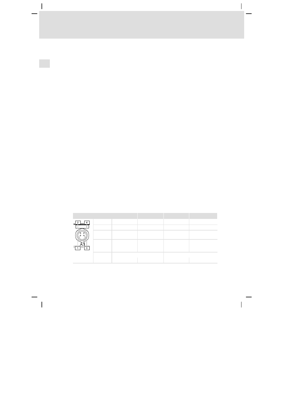
Depending on the bus system of the communication unit, statuses are indicated
by means of an LED display. Detailed information can be found in the
communication manual for the bus system used.
LED
1 (green)
2 (green)
3 (red)
4 (red)
PROFIBUS
BUS STATE
MODULE STATE
BUS ERROR
MODULE ERROR
AS−i
SLAVE 1 READY
SLAVE 2 READY
SLAVE 1 ERROR
SLAVE 2 ERROR
EtherCAT
RUN
LINK/ACTIVITY
ERROR
LINK/ACTIVITY
(green)
PROFINET
BUS READY
LINK/ACTIVITY
1
(yellow)
BUS ERROR
LINK/ACTIVITY 2
(yellow)
EtherNet/I
P
MODULE STATE
NETWORK STATE
E84DG056_b
(red)
(green)