Mp 2xxx dvi / mp 5xxx dvi / mp 9xxx dvi, Mechanical installation – Lenze MP 9000 DVI Operating Instructions User Manual
Page 27
Mechanical installation
Mounting steps
MP 2xxx DVI / MP 5xxx DVI / MP 9xxx DVI
l
27
BA_MP9000DVI DE 4.0
5.3.2
MP 2xxx DVI / MP 5xxx DVI / MP 9xxx DVI
)
Note!
Types MP 5020 DVI, MP 5050 DVI, and MP 5070 DVI can be installed in any
control panel and in 19" mounting racks in accordance with DIN 41494.
Control board mounting
How to perform the installation:
1. Prepare the control board by cutting the mounting cutout and drilling the mounting
holes into it (
¶ 25).
2. Check that the gasket under the front panel is located correctly.
3. Place the device in the mounting cutout, secure it by hand against falling down and
screw the nuts and washers onto the threaded bolts.
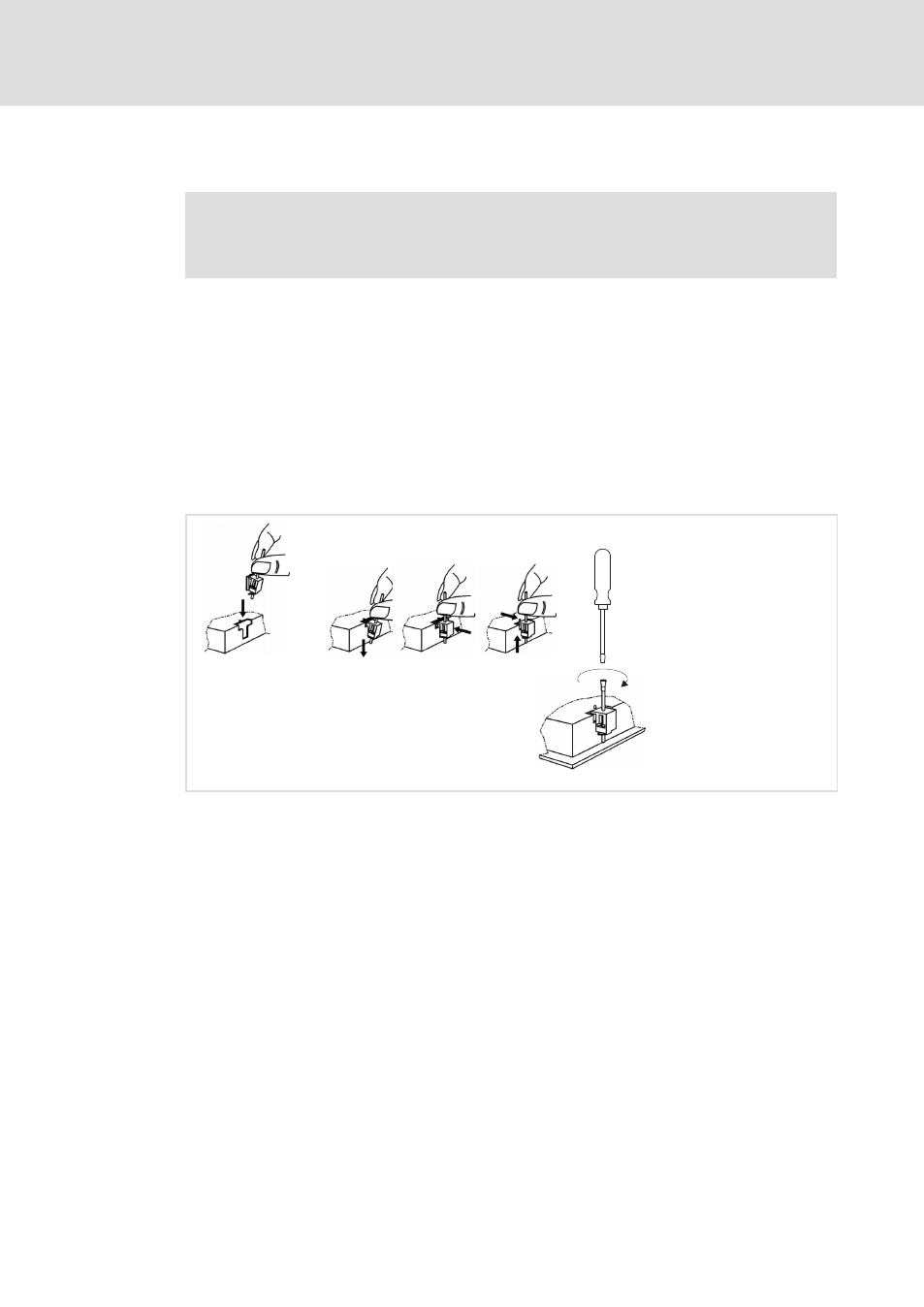
4. Fit all screw clamp fixings as explained below:
ELx7xx−012
– Insert the screw clamp fixing into the slot in the housing of the device (see above
figure).
– Press the screw clamp fixing downwards, tilt it towards the housing and check
that it has firmly snapped into place.
– Tighten the screw clamp fixing hand−tight with a screwdriver.
5. Check that the device is securely located in the mounting cutout and that the front
panel gasket is located correctly.
– If necessary, realign the device/gasket.
– If the gasket is not located correctly, protection class IP65 is not achieved on the
front of the device!
19" mounting rack installation (only MP 5020 DVI, MP 5050 DVI, and MP 5070 DVI)
How to perform the installation:
1. Remove the set screws from the back of the front frame.
2. Drill through the blind holes at the back of the front frame using a 6.5 mm drill.
3. Place the device in the 19" mounting rack and screw it.