Connecting the supply and peripheral devices, Terminal diagram supply, 24 v connection – Lenze MP 9000 DVI Operating Instructions User Manual
Page 30: Electrical installation
Electrical installation
Connecting the supply and peripheral devices
Terminal diagram supply
l
30
BA_MP9000DVI DE 4.0
6.3
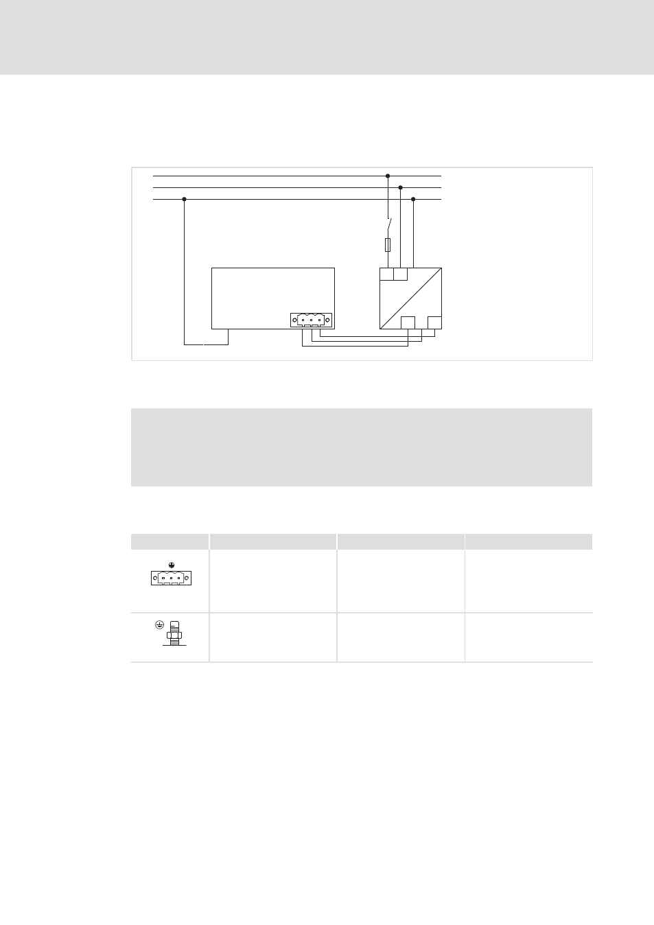
Connecting the supply and peripheral devices
6.3.1
Terminal diagram supply
L1
N
PE
L1 N
+
0V
+24
+
~
=
0 V PE +24 V
+
0
1
F
S
MP9000DVI−006
0 Monitor panel
1 Power supply unit
)
Note!
Observe the max. permissible input voltage.
Professionally fuse the device on the input side against voltage variations and
voltage peaks.
6.3.2
24 V connection
Description
Connection type
Cable type
0V
U
DC 24 V connection
3−pole Phoenix Combicon
socket
Cable (conductor
cross−section max. 2.5 mm
2
)
with Phoenix Combicon plug,
MSTB 2.5 / 3−STF−5.08
IPC001
PE connection
M4 threaded bolt
Separate earthing conductor
(min. 2.5 mm
2
) with ring
cable lug
IPC001
This manual is related to the following products: