Installation – Leica Biosystems CM1950 User Manual
Page 32
32
Instructions for Use V 1.5 RevF - 08/2014
6.5.9 Installing the section extraction (optional) – Use with blade holder CE only
6. Installation
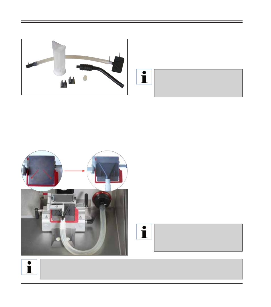
When the suction nozzles are changed, the
adapter (white) remains in the silicone hose. Pull
off the nozzle by rotating and pulling it gently and
firmly plug in the desired nozzle.
A
D
I
B
C
Fig. 30
A
B
C
D
F
E
H
G
Mark
for suction
nozzle
The tension acting on the hose can be minimized
by turning the red ring (
Fig. 31
, top right) clock-
wise so that the suction nozzle presses against
the pressure plate (I,
Fig. 31
).
Afterwards, fold the anti-roll guide (K) back onto
the pressure plate.
• The scope of delivery also includes 2 plastic
clips (H). These enable comfortable "parking"
of the chamber suction nozzle (F) during sec-
tioning.
The clip must be glued in before switching on the
refrigeration. Before doing so, briefly degrease
the surface to ensure a secure hold.
Preferably, the clip should be attached outside
the working area, e.g. on the left inside wall of
the instrument.
Fig. 31
Fig. 32
K
• Silicone hose (A) with hose adapter 1 (B, for filter
in instrument), hose adapter 2 (C, for suction
nozzle D or F) and suction nozzle (D) – factory
pre-assembled
• Silicone stopper (E)
• Chamber suction nozzle (F)
• Filter (G)
• Plastic clips (H), for parking the chamber suction
nozzle.
Ensure that the hose with the nozzle is
not installed against its "natural" curva-
ture on the pressure plate of the knife
holder.
If the suction nozzle (D) is not being
used, it can be "parked" on one of the
two magnetic surfaces indicated in the
interior of the instrument.
If the extraction is not used for a long time, it is absolutely necessary to clean the extraction hose in order
to ensure maximum extraction capacity. To do so, place the hose in commercially available disinfectant or
alcohol. After several cleanings, the hose must be replaced (
see Chap. 11.1
)!