Icm-505 overview – Koolance ICM-505 User Manual
Page 9
4
4
Introduction
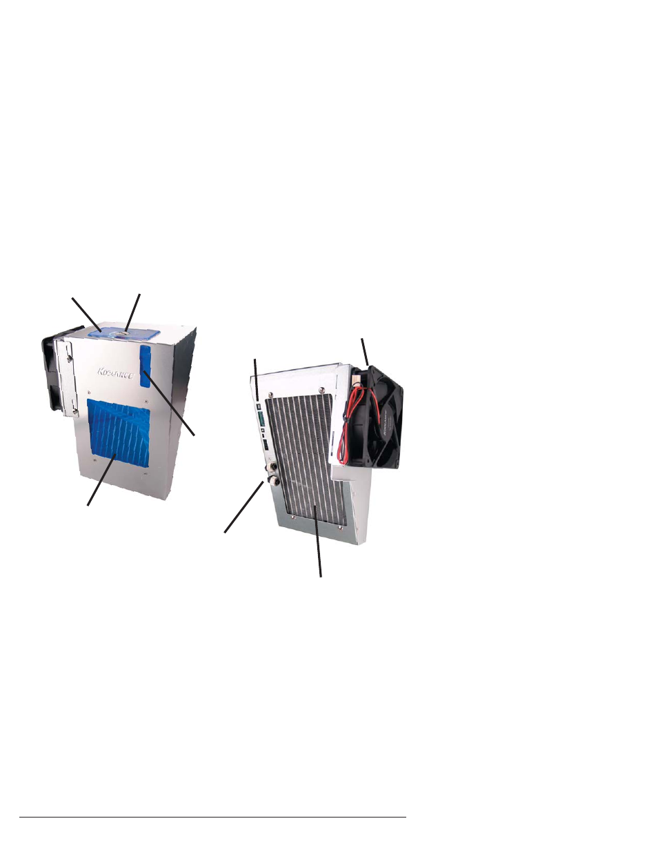
ICM-505 Overview
Reservoir & Pumps
Radiator Cooling Fan
Reservoir Refi ll Plug
Radiator (Primary Heat Exchanger)
Power Circuit
Connections
Coolant Inlet / Outlet
Nozzles
Reservoir & Pumps - The coolant tank is translucent for easy liquid-level monitoring.
Dual pumps help to provide higher system reliability; if one pump should fail, the
other can maintain fl ow, gradually bringing the system to shut itself down (see
LED Display Panel).
Power Circuit Board - The Power Circuit is responsible for a number of tasks,
including: powering the pumps, LED display (sold separately), heat exchanger
fans, and operating the audio alarm and shutdown modes.
Radiator - The primary heat exchanger is located beneath the fan cooling module.
This is the main cooling element, and provides high thermal dissipation in a
relatively small area. Inside, an aluminum mesh (Louver fi n) is webbed between
13 horizontal liquid paths.
Coolant Level
Window
Radiator Window