Connection diagram – JUMO 701550 di 308 - Digital Indicator Data Sheet User Manual
Page 6
2012-05-30/00485042
Data Sheet 701550
JUMO GmbH & Co. KG • 36035 Fulda, Germany
Page 6/7
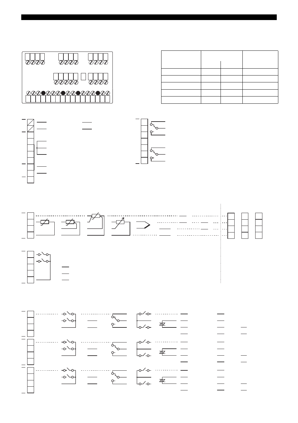
Connection diagram
Terminal strip 3
Terminal strip 2
Terminal strip 1
1
2
3
4
1
2
3
4
5
6
7
8
6
7
8
9
10
9
10
11
12
4
L1(L+)
5
6
8
9
11
12
13
15
16
17
N(L+)
Option 1
Option 2
Option 3
Terminal strip 1
(option slots)
Terminal strip 2
Terminal strip 3
Conductor cross-sections and core-end ferrules for installation
Core-end ferrule
Conductor
cross-section
Min. length of
core-end ferrule
or stripped
min.
max.
without ferrule
0.34mm
2
2.5mm
2
10mm (stripped)
without lip
0.25mm
2.5mm
2
10mm
with lip up to 1.5mm²
0.25mm
2
1.5mm
2
10mm
with lip from 1.5mm²
1.5mm
2
2.5mm
2
12mm
twin, with lip
0.25mm
2
1.5mm
2
12mm
L1
N
L+
L-
4
5
6
8
110—240V AC
20—30V AC/DC
Supply voltage for
2-wire transmitter
(off-load voltage: approx. 25V)
Supply
9
+
-
U
=
15.8—15.2V /
30—50mA
U
=
L1
L+
N
L-
230V/3A
Relays
12
11
13
15
16
17
Ö
P
S
Ö
P
S
230V/3A
Binary output 1
Binary output 2
1
2
4
3
6
7
8
E
S
A
-
+
-
+
I
x
I
x - /
~
~
RTD
RTD
RTD
Resistance
transmitter
Thermo-
couple
Current
Voltage
0(2)—10V
Binary input
1+2
1
2
GND
Binary output
3+4
(logic 12V)
3 (+)
4 (+)
GND (-)
Input 1
Binary
9
10
Voltage
0—1V
U
x
-
+
U
x
-
+
1
2
4
3
5
6
8
7
9
10
12
11
Option 1
Option 2
Option 3
Terminal assignment of strip 1
for analog input 2
1
2
4
3
Analog
input
2 binary
inputs
Analog
output
Relay,
changeover
(SPDT)
2 relays,
make
(SPST-NO)
PROFIBUS
RS422
3
4
GND
+
-
U
x
Ö
P
S
5
8
RxD +
RxD -
TxD +
TxD -
RS485
RxD/TxD +
RxD/TxD -
Solid-state
relay
Analog input 2,
connection as for
analog input 1
Binary input 3+4
Analog output 5
Binary output 5
Binary output 5+8 Binary output 5
5
6
8
7
5
6
GND
+
-
RxD +
RxD -
TxD +
TxD -
RxD/TxD +
RxD/TxD -
Analog input 2,
connection as for
analog input 1
Binary input 5+6
Analog output 6
Binary output 6
Option 1
Option 2
Ö
P
S
Binary output 6
6
9
Binary output 6+9
9
10
12
11
7
8
GND
+
-
RxD +
RxD -
TxD +
TxD -
RxD/TxD +
RxD/TxD -
Analog input 2,
connection as for
analog input 1
Binary input 7+8
Analog output 7
Binary output 7
Option 3
Ö
P
S
Binary output 7
7
10
Binary output 7+10
/ I
x
U
x
/ I
x
U
x
/ I
x
VP (+5 V)
RxD/TxD-P (B)
RxD/TxD-N (A)
DGND
VP (+5 V)
RxD/TxD-P (B)
RxD/TxD-N (A)
DGND
VP (+5 V)
RxD/TxD-P (B)
RxD/TxD-N (A)
DGND
Terminal strip 1