JUMO 701550 di 308 - Digital Indicator Data Sheet User Manual
Jumo di 308, Block structure, Key features
Page 1/7
JUMO GmbH & Co. KG
Delivery address: Mackenrodtstraße 14
36039 Fulda, Germany
Postal address:
36035 Fulda, Germany
Phone:
+49 661 6003-0
Fax:
+49 661 6003-607
E-mail:
Internet:
www.jumo.net
JUMO Instrument Co. Ltd.
JUMO House
Temple Bank, Riverway
Harlow, Essex CM20 2DY, UK
Phone: +44 1279 635533
Fax:
+44 1279 635262
E-mail:
Internet: www.jumo.co.uk
JUMO Process Control, Inc.
8 Technology Boulevard
Canastota, NY 13032, USA
Phone:
315-697-5866
1-800-554-JUMO
Fax:
315-697-5867
E-mail:
Internet: www.jumo.us
Data Sheet 701550
2012-05-30/00485042
JUMO di 308
Digital Indicator, microprocessor-controlled,
with max. 2 inputs, wide range of expansion options,
panel-mounting DIN housing, bezel 96mm x 48mm
Brief description
The JUMO di 308 indicator shows temperatures in °C or °F, and standard signals in plain text.
Even the basic instrument is provided with one analog input, two binary inputs, two relay
outputs, two logic outputs, and a supply voltage for a 2-wire transmitter. Three expansion slots
can be filled with additional inputs, outputs and interfaces.
The high-contrast, multicolor LCD for showing measurements and for operator prompting
consists of a 5-digit 7-segment display (for the measurement or for setting parameters), an 8-
character 16-segment display with color changeover (for the value, parameter name, channel
name, process/alarm text as a running text of max. 24 characters, or a pseudo bar graph), and
4 switch status indicators for the binary outputs.
Four keys are provided on the instrument for operation and configuration, and a setup program
for PC use is available as an option (e.g. for configuring the math and logic functions, and the
input of display texts).
Linearizations for the usual transducers are stored, a customer-specific linearization table can
be programmed through 10 interpolation points or by entering the coefficients of the
polynomial.
An RS422/485 or a PROFIBUS-DP interface can be used to integrate the instrument into a data
network. The electrical connection is made at the back, via screw terminals.
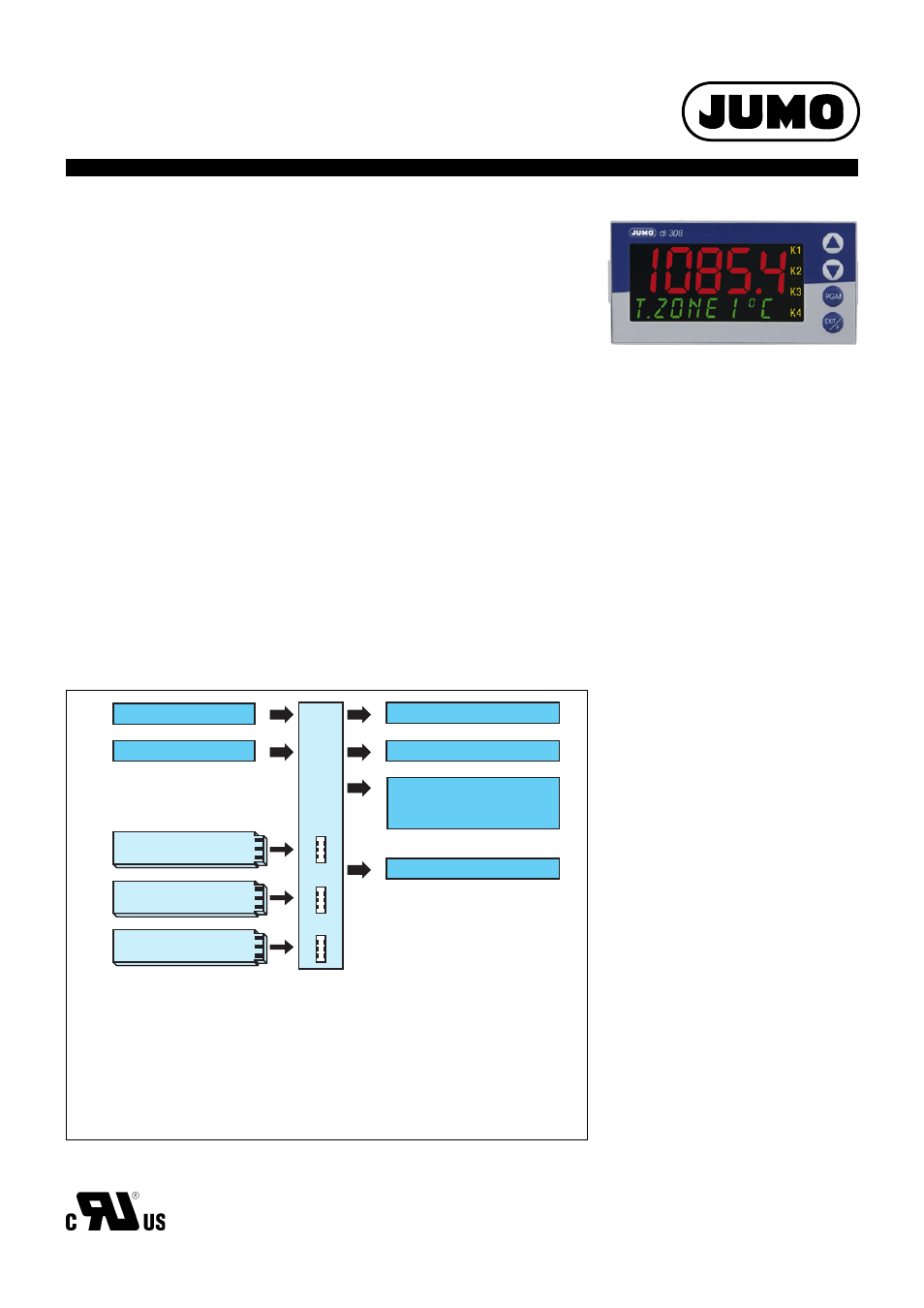
The possible input and output configurations are shown in the following block diagram.
Block structure
Analog input
Option 1
Option 2
2 binary inputs
2 relays, changeover (SPDT)
2 logic outputs
Supply for
2-wire transmitter
Option 3
Setup interface
Option boards:
– Analog input
– 2 binary inputs
– 1 relay 230V/8A, changeover (SPDT)
– 2 relays 230V/3A, make (SPST-NO), with common pole
– 1 solid-state relay
– Analog output (voltage/current)
– RS422/485 interface
– PROFIBUS-DP interface
Key features
k Configurable process display text
(max. 24-character running text)
k Alarm signal text with color changeover
green-red (also as running text)
k Up to two configurable
analog inputs
k Three option slots
k Math and logic module (option)
k 4 limit comparators
k Fast and convenient configuration
through setup program
k RS422/485 interface (option)
k PROFIBUS-DP interface (option)
JUMO di 308
Type 701550/...
Approvals/marks of conformity
(see Technical data)