Customized linearization, User data, Math and logic module (extra code) – JUMO 701550 di 308 - Digital Indicator Data Sheet User Manual
Page 5: Binary functions, Functions of the outputs, Setup program for pc (accessory), Interfaces, Displays and controls, Dimensions side-by-side mounting
2012-05-30/00485042
Data Sheet 701550
JUMO GmbH & Co. KG • 36035 Fulda, Germany
Page 5/7
Customized
linearization
In addition to the linearizations for the usual
transducers, a customer-specific linearization
can be created. The programming is carried
out in the setup program, in the form of a table
of values (10 value pairs) or a formula
(coefficient entry of polynomial).
User data
Parameters which frequently have to be
changed by the user can be combined at the
user level, under “User data” (only through the
setup program).
Math and logic module
(extra code)
The math module makes it possible to
integrate measurements from the analog
inputs into a mathematical formula, so that
the calculated process variable is displayed.
The logic module can be used, for instance, to
make a logical combination of binary inputs
and limit comparator states.
Up to two math or logic formulae can be
entered through the setup program, and the
results of the calculations can be presented at
the outputs or via the display.
Binary functions
– key/level inhibit
– display off
– text display
– color changeover
– resetting MIN/MAX values
– “hold” function
– acknowledge limit comparators
– taring function
– resetting the taring function
– jump to next scroll parameter
The logic functions can be combined with one
another (only through the setup program).
Functions of the
outputs
– analog input variables
– math
– limit comparators
– binary inputs
– logic formula
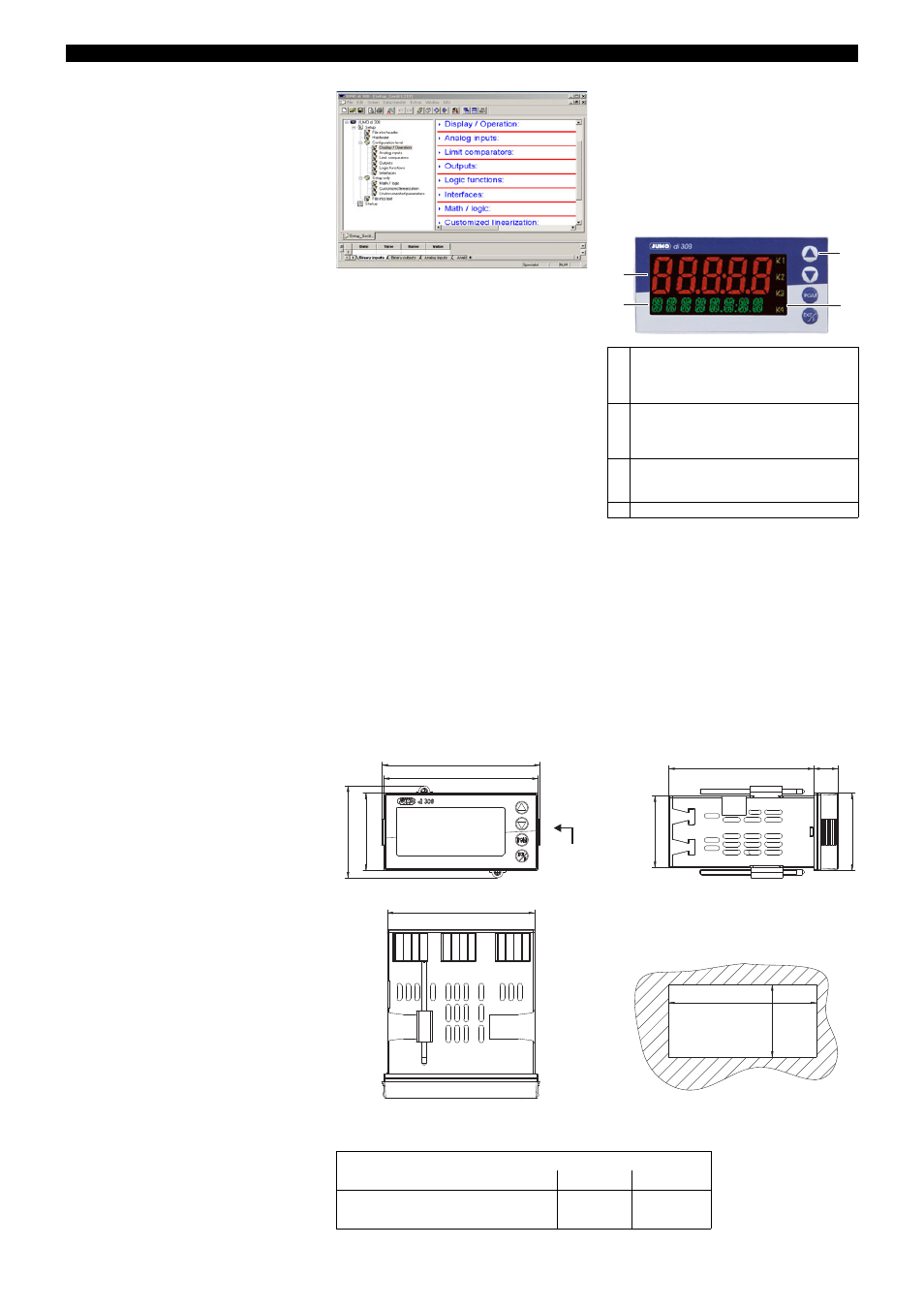
Setup program for PC
(accessory)
The PC setup program for configuring the
instrument is available in English, French,
German and other languages. It can be used
to create and edit data sets, transfer them to
the instrument or read them out from it. The
data can be saved and printed.
The program includes a startup function for
recording and visualizing measurement data.
Interfaces
Setup interface
The setup interface is integrated as standard
in the indicator. It can be used to configure the
instrument, in conjunction with the setup
program (accessory) and setup interface
(accessory).
RS422/RS485 interface
The serial interface serves for communication
with supervisory systems, using the Modbus
protocol.
PROFIBUS-DP
The indicator can be integrated into a field
bus system according to the PROFIBUS-DP
standard via the PROFIBUS-DP interface.
This PROFIBUS version is especially
designed for communication between
automation systems and decentralized
peripheral devices at the field level, and
optimized for speed.
Data transmission is made serially, using the
RS485 standard.
GSD generator, the project-planning tool that
is supplied with the package (GSD =
Gerätestammdaten, i.e. device data), is used
to make a selection of device characteristics
for the indicator, to create a standardized
GSD file that is used to integrate the indicator
into the field bus system.
Displays and
controls
(1)
7-segment display (measurement display)
5-digit, red; configurable decimal place
(automatic adjustment on
display overflow)
(2)
16-segment display (24-character running
text, parameter name, level symbols)
8-character, green or red;
configurable decimal place
(3)
Indication
yellow; for four switching states of max.
four outputs (indicator lit up = on)
(4)
Keys
(4)
(2)
(1)
(3)
Dimensions
Side-by-side mounting
Minimum spacing of panel cut-outs
horizontal
vertical
without setup plug:
30mm
11mm
with setup plug (see arrow):
65mm
11mm
57.1
96
99
48
44.5
92
+0.8
45
+0.8
15
48
90
91.5
PC
interface
adapter
Panel cut-out