Connection diagram, Connection diagram (sensor) – JUMO 902940 DELOS T Electronic Temperature Switch with Display and Analog Output Data Sheet User Manual
Page 5
2012-09-28/00536576
Data Sheet 902940
Page 5/17
JUMO GmbH & Co. KG
Delivery address: Mackenrodtstraße 14
36039 Fulda, Germany
Postal address:
36035 Fulda, Germany
Phone:
+49 661 6003-0
Fax:
+49 661 6003-607
E-mail:
Internet:
www.jumo.net
JUMO Instrument Co. Ltd.
JUMO House
Temple Bank, Riverway
Harlow, Essex CM20 2DY, UK
Phone: +44 1279 635533
Fax:
+44 1279 635262
E-mail:
Internet: www.jumo.co.uk
JUMO Process Control, Inc.
8 Technology Boulevard
Canastota, NY 13032, USA
Phone: 315-697-5866
1-800-554-JUMO
Fax:
315-697-5867
E-mail:
Internet: www.jumousa.com
Connection diagram
The connection diagram in the data sheet provides preliminary information about the connection possibilities. For the electrical connection only
use the installation instructions or the operating manual. The knowledge and the correct technical execution of the safety information/instructions
contained in these documents are mandatory for installation, electrical connection, and startup as well as for safety during operation.
The connection is located on the rear of the temperature switch!
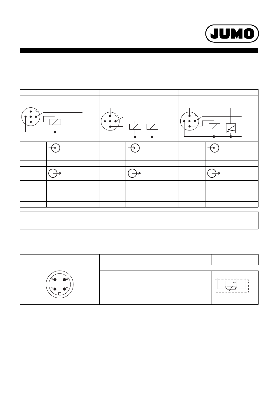
Connection diagram (sensor)
Order code 470
Order code 471
Order codes 475, 476, and 477
1× PNP switching output
2× PNP switching output
1× PNP switching output
and 1× analog output
Voltage
supply
Voltage
supply
Voltage
supply
1 L+
DC 12 to 30 V
1 L+
DC 12 to 30 V
1 L+
DC 12(14) to 30 V
3 L-
GND
3 L-
GND
3 L-
GND
Output
Output
Output
4 K1
Highside Open Collector
max. 0.25 A
2 K2
Highside Open Collector
max. 0.25 A
2 analog
0(4) to 20 mA/0 to 10 V
2
nc
4 K1
4 K1
Highside Open Collector
max. 0.25 A
5
Interface
5
Interface
5
Interface
Assignment: M12 × 1 machine connector
1 bn
Brown
4 bk
Black
The assignment only applies to A-coded stan-
dard cables.
2 wh
White
5 gy
Gray
3 bu
Blue
Machine connector M12 × 1, 4-pin
according to IEC 60947-5-2
Electrical connection
Terminal assignment
Basic type 902940/50
RTD temperature probe in 4-wire circuit
(input)
Top view of the machine connector at the
corresponding RTD temperature probe!
1
2
3
4
5
L-
K1
L+
1
2
3
4
5
L-
K1
K2
L+
1
2
3
4
5
L-
K1
L+
1
2
3
4