7 technical data – JUMO 706560 LOGOSCREEN es Installation Instructions User Manual
Page 27
27
7 Technical data
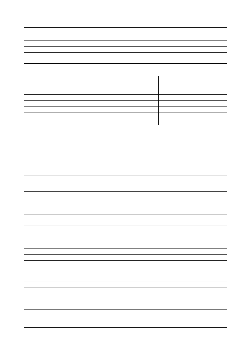
Transducer short-circuit/break
Logic inputs (extra code)
Outputs
External analog inputs / logic inputs / logic outputs
Screen
Range start/end
freely programmable within the limits in 0.1 mA steps
Sampling cycle
6 or 12 channels 125msec
Input filter
2nd order digital filter; filter constant adjustable from 0 to 10.0sec
Feature
adjustable linearizations for thermocouples and resistance thermometers
(for connection of transmitters without linearization)
Short-circuit
1
Break
1
Thermocouple
not detected
detected
Resistance thermometer
detected
detected
Resistance transmitter
detected
detected
Potentiometer
not detected
detected
Voltage up to ± 1V
not detected
detected
Voltage > ± 1V
not detected
not detected
Current
not detected
not detected
1. programmable reaction of instrument, e.g. triggering alarm
Number
7 to DIN VDE 0411, Part 500;
max. 25Hz, max. 32V
Level
logic “0“: -3 to +5V,
logic “1”: 12 to 30V
Sampling cycle
minimum 1sec
1 relay (ex-factory)
changeover, 3A, 230V AC
1
4 relays (extra code)
make/break, 3A, 230V AC
1
1 open-collector output
(extra code)
max. 25V, max. 100mA
1 voltage output
(extra code)
24V DC, 50mA
1. with resistive load. SELV circuits and supply circuits must not be combined.
Type
JUMO mTRON automation system
Sampling cycle
1sec
Technical data
see Data Sheet:
70.4015 Relay module
70.4020 Analog input module
70.4030 Logic module
Configuration
Project design software iTOOL (70.4090)
Resolution
320 x 240 pixels
Size
5.7"
Number of colors
27 colors