12 safety cut-out in the power section, Safety cut-out in the power section, Adjusting the output level signal (output adjust u – JUMO 709050 IPC IGBT Power Converter IPC 70/100A Operating Manual User Manual
Page 43: Chapter 5.12 „safety cut-out in the power section, 5 settings, P , i
02.08 [IGBT Power Converter 70/100A]
43
5 Settings
5.12 Safety cut-out in the power section
If there is a fault in the choke or the control electronics, the output voltage is
switched off between terminals D and 1D.
This state is indicated by the „IGBT“ LED, and the fault signal relay drops out.
This safety cut-out remains activated even when the fault has been remedied.
It can only be reset by disconnecting the voltage supply.
h Switch the device off briefly, and then on again
5.13 Adjusting the output level signal (output adjust U
2
, P , I
2
)
In the factory settings, the output level signal corresponds to the I
2
signal at
the output of the converter. It is thus proportional to the power in the load
(R=constant).
However, setting P or U
2
instead of the I
2
signals is also possible
v Chapter 5.2 „Setting switches S101, S103, S104, S105, S106 and X106“
Output adjust
U
2
, P, I
2
The output level signal provides a voltage in the range of 0 to 10V
(corresponding to 0 to 100% of the variable being measured). The trimmer
„output adjust U
2
, P , I
2
“ on the front panel can be used to set the required
end value:
A
However, terminals D and 1D may still carry dangerous voltage from
the supply. They are not electrically isolated from the supply!
Power level output
Internal switches
S4
S5
S6
U
2
1
0
0
P
0
1
0
I
2
0
0
1
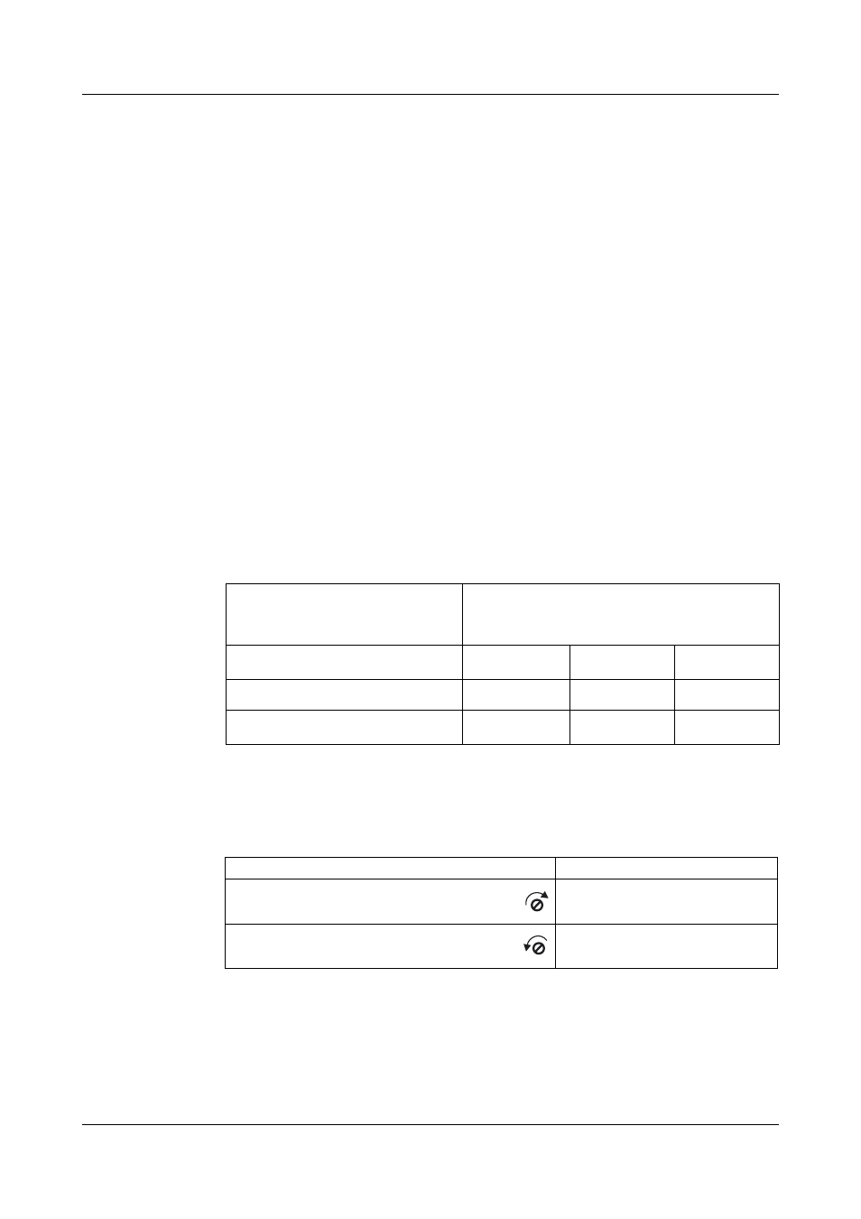
Action
Response
Turn „output adjust U
2
, P , I
2
“ trimmer
clockwise
End value increases
Turn „output adjust U
2
, P , I
2
“ trimmer
counter-clockwise
End value reduces