Connection diagram – JUMO 709062 TYA 202 - Three-Phase Power Controller Data Sheet User Manual
Page 10
2012-12-31/00561069
Data sheet 709062
Page 10/17
JUMO GmbH & Co. KG
Delivery address: Mackenrodtstraße 14
36039 Fulda, Germany
Postal address:
36035 Fulda, Germany
Phone:
+49 661 6003-0
Fax:
+49 661 6003-607
E-mail:
Internet:
www.jumo.net
JUMO Instrument Co. Ltd.
JUMO House
Temple Bank, Riverway
Harlow, Essex CM20 2DY, UK
Phone: +44 1279 635533
Fax:
+44 1279 635262
E-mail:
Internet: www.jumo.co.uk
JUMO Process Control, Inc.
8 Technology Boulevard
Canastota, NY 13032, USA
Phone: 315-697-5866
1-800-554-JUMO
Fax:
315-697-5867
E-mail:
Internet: www.jumousa.com
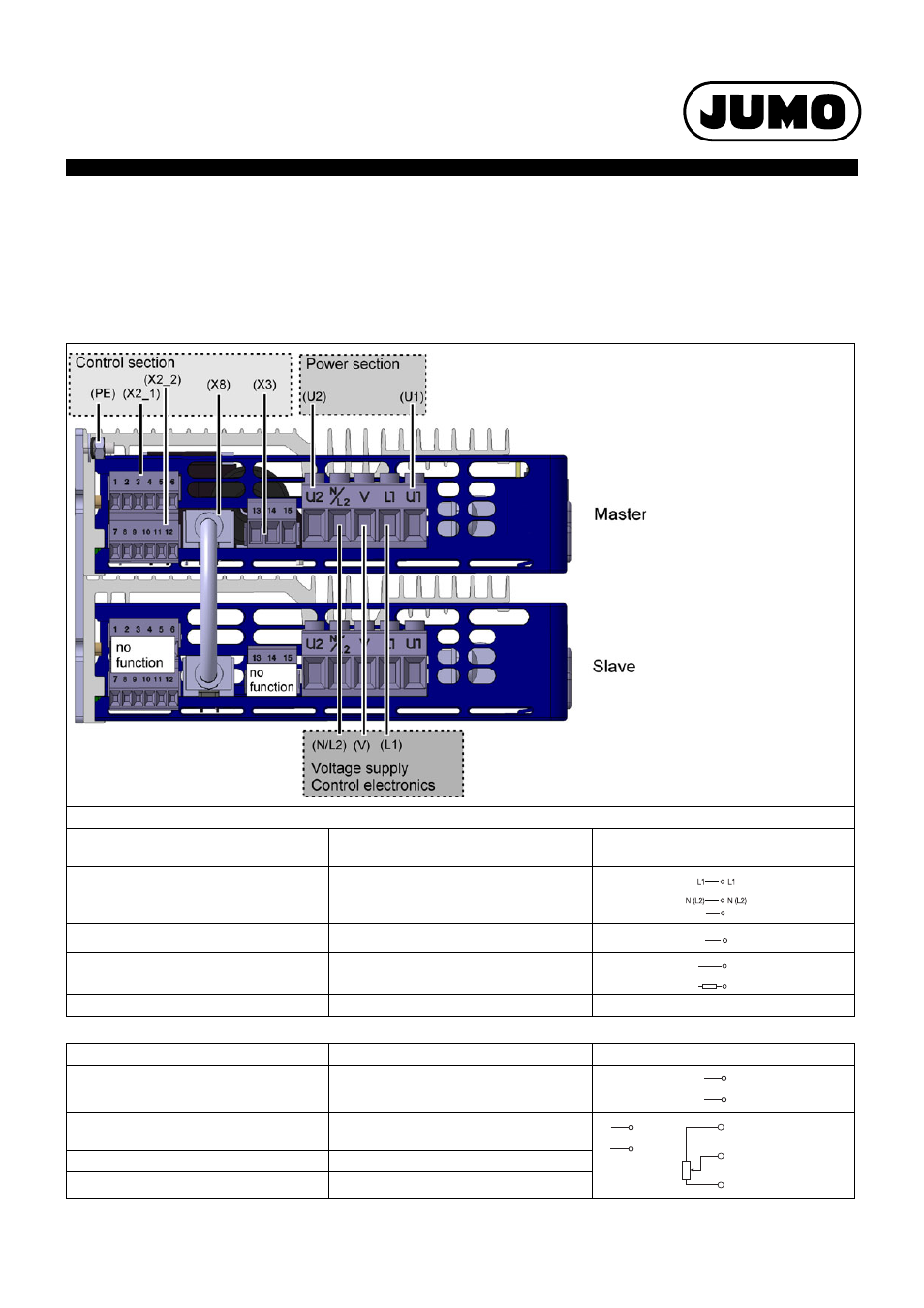
Connection diagram
The connection diagram contained in the data sheet provides a first information about the connection possibilities. Only use the installation
instructions or the operating manual for the electrical connection. The knowledge and the correct technical execution of the safety information/
instructions contained in these documents are prerequisite for installation, electrical connection and commissioning/start-up as well as for safety
during operation.
Typ 709062/X-0X-20-XXX-XXX-XX-25X
Control section
Power section
Connection for
screw terminals control section/
power section
Detail
Voltage supply Control electronics
(is the same as the max. Load voltage of the
ordered Type, see order matrix)
L1
N/L2
V
Protective earth
PE
Load connection
U1
U2
Fan X14
20, 21 (only types with load current 250A)
Connection for
Screw terminal X2_1
Detail
Setpoint value input current
1
2
Setpoint value input voltage
3 (GND)
4
Output DC 10V fixed voltage
5
Ground potential
6 (GND)
Note:
Master-Slave connection is already established and de-
vice configuration is set (factory setting). The device is
ready for connection of the load and the voltage supply.
V
V
PE
PE
U2
U1
N/L2
L1
2
1
+
–
I
x
Example for exter-
nal manual mode
via potentiometer
4
3
+
–
U
x
E
S
A
3
4
5
5k
W