Connection diagram, Analog inputs – JUMO 705010 mTRON T - Multichannel Controller Module Data Sheet User Manual
Page 10
JUMO GmbH & Co. KG
Delivery address: Mackenrodtstraße 14
36039 Fulda, Germany
Postal address:
36035 Fulda, Germany
Phone:
+49 661 6003-0
Fax:
+49 661 6003-607
E-mail:
Internet:
www.jumo.net
JUMO Instrument Co. Ltd.
JUMO House
Temple Bank, Riverway
Harlow, Essex CM20 2DY, UK
Phone: +44 1279 635533
Fax:
+44 1279 635262
E-mail:
Internet: www.jumo.co.uk
JUMO Process Control, Inc.
6733 Myers Road
East Syracuse, NY 13057, USA
Phone: 315-437-5866
1-800-554-5866
Fax:
315-437-5860
E-mail:
Internet: www.jumousa.com
2013-05-07/00529107
Data Sheet 705010
Page 10/15
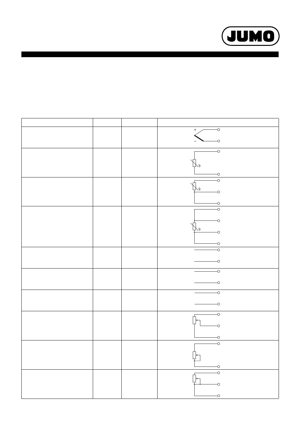
Connection diagram
The connection diagram included in the data sheet provides initial information about the connection options. Only use the installation instructions
or the operating manual for the electrical connection. The know-how and the correct technical implementation of the safety warnings/instructions
contained in these documents are the prerequisite for the installation, electrical connection, and initial start as well as for the safety during opera-
tion.
Analog inputs
Input 1, 2: Standard version; input 3, 4: Option
Connection
Input
Terminals
Symbol and terminal designation
Thermocouple
1
2
3
4
2 and 3
6 and 7
18 and 19
22 and 23
2, 6, 18, 22
3, 7, 19, 23
RTD temperature probe
2-wire circuit
1
2
3
4
2 and 4
6 and 8
18 and 20
22 and 24
2, 6, 18, 22
4, 8, 20, 24
RTD temperature probe
3-wire circuit
1
2
3
4
2 to 4
6 to 8
18 to 20
22 to 24
2, 6, 18, 22
3, 7, 19, 23
4, 8, 20, 24
RTD temperature probe
4-wire circuit
1
2
3
4
1 to 4
5 to 8
17 to 20
21 to 24
1, 5, 17, 21
2, 6, 18, 22
3, 7, 19, 23
4, 8, 20, 24
Voltage DC 0(2) to 10 V
1
2
3
4
1 and 2
5 and 6
17 and 18
21 and 22
1, 5, 17, 21
2, 6, 18, 22
Voltage DC 0 to 1 V
1
2
3
4
2 and 3
6 and 7
18 and 19
22 and 23
2, 6, 18, 22
3, 7, 19, 23
Current DC 0(4) to 20 mA,
Heater current AC 0 to 50 mA
1
2
3
4
3 and 4
7 and 8
19 and 20
23 and 24
3, 7, 19, 23
4, 8, 20, 24
Resistance transmitter
A = Start
E = End
S = Slider
1
2
3
4
2 to 4
6 to 8
18 to 20
22 to 24
2, 6, 18, 22
3, 7, 19, 23
4, 8, 20, 24
Resistance/potentiometer
2-wire circuit
1
2
3
4
2 and 4
6 and 8
18 and 20
22 and 24
2, 6, 18, 22
4, 8, 20, 24
Resistance/potentiometer
3-wire circuit
1
2
3
4
2 to 4
6 to 8
18 to 20
22 to 24
2, 6, 18, 22
3, 7, 19, 23
4, 8, 20, 24
U
+
-
x
U
+
-
x
I
+
-
x
E
S
A