4 functional test, Functional test, 3 electrical connection – JUMO 705040 mTRON T - Router Module Installation Instructions User Manual
Page 29
29
3 Electrical connection
3.4
Functional test
Once the electrical connection is complete, the following points must be checked:
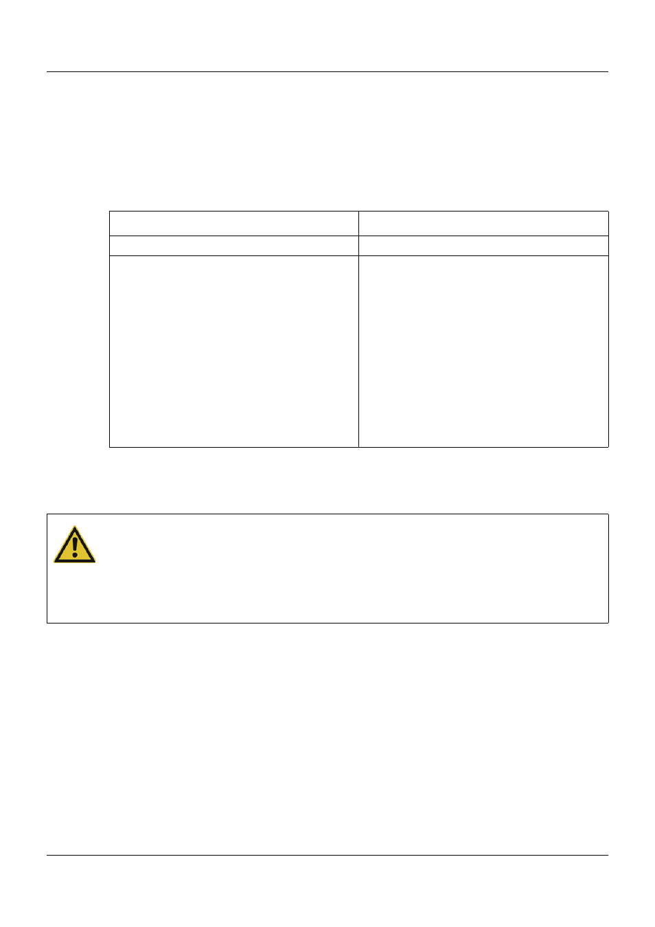
1) Voltage supply
2) Connection to system bus
Voltage supply
Connection to system bus
The "Bus In" input must be connected to the "Bus Out" output of a base unit or of an upstream
multifunction panel or router module.
Startup
The checks described above complete the process of installation and electrical connection. For
the startup, the router module is integrated into the system through the definition of the hard-
ware arrangement in the setup program. The router module itself does not need to be config-
ured.
System description B 705000.8
Setup program manual B 705000.6
The "Introduction" section of this document contains an overview of all documentation for the
measuring, control, and automation system.
Signal
Meaning
LED "P" (Power) is lit
The router module is supplied with voltage.
LED "P" (Power) is not lit
The router module is not supplied with voltage or
there is a problem with the electrical function of
the LED.
Remedy:
•
Check voltage supply at the "+24 V" and
"GND" terminals of the router module.
•
Check power supply unit and connection be-
tween the power supply unit and the router
module.
If the "Power" LED does not light up despite a
voltage supply being present, the module insert
or – if the bus board inside the case is faulty – the
entire router module must be replaced.
CAUTION!
Under certain circumstances, swapped connection cables for Bus In, Bus Out1, and
Bus Out2 are not detected by the system.
The system then starts with reversed strands.
To avoid this situation, the connection cables for Bus In, Bus Out1, and Bus Out2 must be
labeled clearly. If necessary, the strands can be identified through the serial number of the
modules.