2 installation/dismounting on din rail, Installation/dismounting on din rail, 2 mounting – JUMO 705040 mTRON T - Router Module Installation Instructions User Manual
Page 18
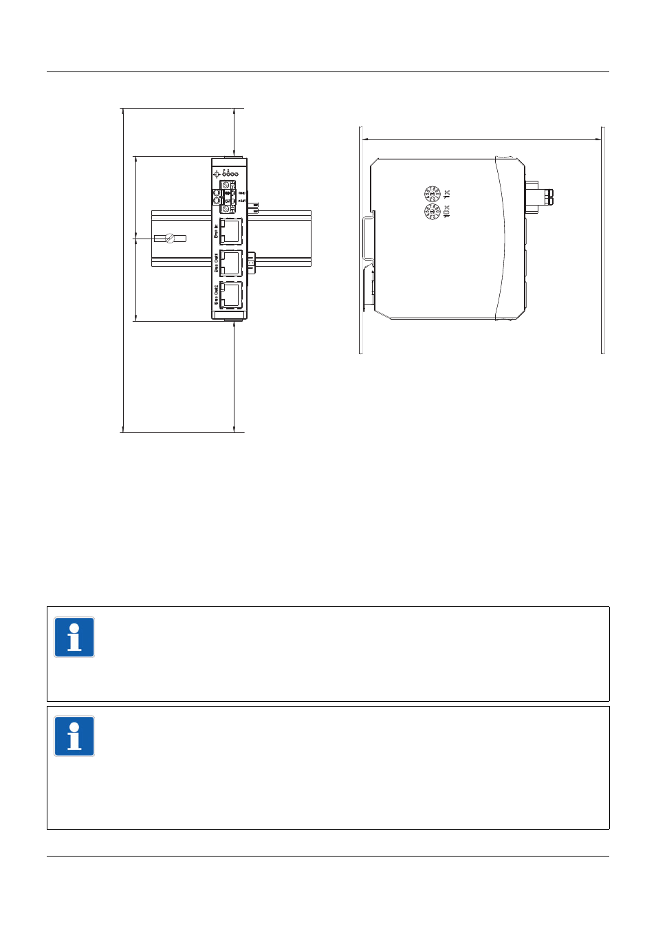
2 Mounting
18
Minimum distances
2.2
Installation/dismounting on DIN rail
All modules in the system are intended for installation on a DIN rail according to DIN EN 60715
(35 mm × 7.5 mm × 1 mm).
The following must always be installed on the left, at the start of the DIN rail:
•
A central processing unit or
•
A router module
These modules connect the input/output modules to the voltage supply and the system bus.
150
203.6 51.8
30
70
51.8
TIP!
To determine the required minimum width of the DIN rail, the widths of the individual modules
are to be added (see technical data of the modules in the respective data sheet or the
module-specific installation instructions).
The widths of the cover (17.5 mm) and both end brackets (each 9.5 mm) should also be
taken into consideration: 17.5 mm + 2 × 9.5 mm = 36.5 mm.
TIP!
Two rotary coding switches for setting the alias device address are located on the router mod-
ule's left side. If necessary, the setting should be done before the router module is mounted.
Otherwise one has to ensure that the rotary coding switches are still accessible after mount-
ing.
The "10x" switch is used to set the tens digit of the alias device address, the "1x" switch is
used for the unit digit. For more information about setting the alias device address please re-
fer to the setup program manual B 705000.6 (chapter "Hardware arrangement").