Johnson Systems CD-3000 Series Retrofit Control System User Manual
Page 8
8
• Note the location and function of all control cables landed on the circuit
board on top of the processor housing. Label cables if necessary.
These control cables may now be disconnected from the circuit board.
Disconnect the “TOP COLUMNS” and “BOTTOM COLUMNS” control
cables making sure they have their respective labels.
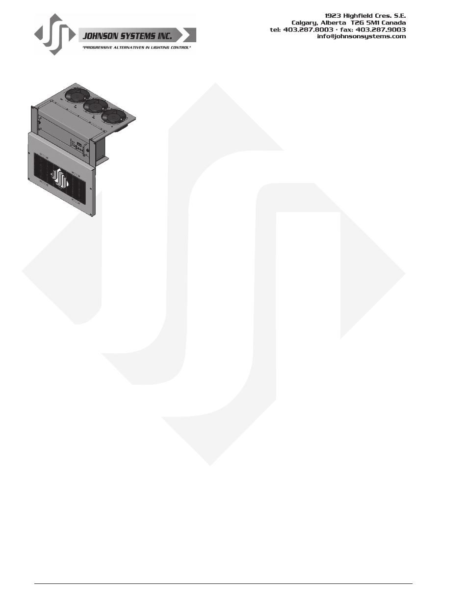
• The processor housing can now be carefully withdrawn from the rack,
threading the control cables out from under the plexiglass cover.
The back end must be supported as it is withdrawn so the power
connector (square, white, 12-position connector) located at the left rear
can be disconnected. To disconnect, squeeze the tabs on both sides of
the connector together and pull out. The processor housing may now be
fully removed and set aside.
• Unscrew and remove the blank panel located under the slot for the
processor housing.
• Unscrew and remove the air filter grill on the fan housing located above
the slot for the processor housing.
• Unscrew and remove the fan housing. There is a Molex connector at
the rear of the fan housing that must be disconnected. This connector
and cable is not required on the CD-3000 retrofit and should be coiled
up and wire-tied to the wiring harness it emerges from. Keep it isolated
from any AC line voltage.
• With everything removed, look at the fuse block in the back of the rack
and check the phasing. The wires landed on the bottom of the fuse
block lead to the processor power connector. The black wire should
be on Phase “A”, red on Phase “B”, and blue on Phase “C”. Correct if
necessary.
Installation of the new CD-3000-SV System
• Remove your new CD-3000-SV system from the box. Leave the foam
end caps in place to protect the unit from damage.
• Familiarize yourself with the backplane, and low voltage control input/
output connections. Refer to page 12 for details.
• Dress out all DMX and other low voltage connections to the backplane
using the breakaway connectors provided. Be sure to isolate and protect
all shield wires.
• Place the CD-3000-AE in front of the rack face down / backplane up.
Leave the foam end caps left in place to protect the unit from
damage.
• Connect the “TOP COLUMNS” and “BOTTOM COLUMNS” control
cables to their designated locations on the backplane. Lock in place
using the ejection clamps on the connector. Refer to page 11 for the
connector pinout.